Sanyo VCC-N6695P Instruction Manual
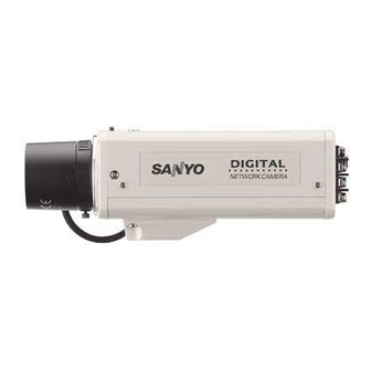
Color ccd camera
Hide thumbs
Also See for VCC-N6695P:
- Brochure (19 pages) ,
- Instruction manual (100 pages) ,
- Installation manual (48 pages)
Table of Contents
Advertisement
Quick Links
Download this manual
See also:
Installation Manual
INSTRUCTION MANUAL
Color CCD Camera
THIS INSTALLATION SHOULD BE MADE BY A QUALIFIED
SERVICE PERSON AND SHOULD CONFORM TO ALL LOCAL
CODES.
Please read this instruction manual carefully in order to ensure correct installation. In addition,
be sure to read carefully the electronic manual contained in the supplied CD-ROM to ensure
correct operation of the camera.
This manual covers 3 models. Any difference between the 3 models is indicated when
necessary.
VCC-N6584
VCC-N6695P
VCC-N4598PC
Advertisement
Table of Contents

Related Manuals for Sanyo VCC-N6695P


Summary of Contents for Sanyo VCC-N6695P
-
Page 1: Instruction Manual
INSTRUCTION MANUAL Color CCD Camera THIS INSTALLATION SHOULD BE MADE BY A QUALIFIED SERVICE PERSON AND SHOULD CONFORM TO ALL LOCAL CODES. Please read this instruction manual carefully in order to ensure correct installation. In addition, be sure to read carefully the electronic manual contained in the supplied CD-ROM to ensure correct operation of the camera. -
Page 2: Table Of Contents
Contents Information to User ...2 Preparations ...4 Parts Names and Functions ...5 Viewing Live Images on a Monitor (Basic Connections) ...6 Camera Settings ...7 Viewing Live Images on a Computer (Network Connection) ...9 Network Settings ...12 Setting the Camera from the Computer...14 Using the Supplied CD-ROM...16 Specifications ...17 ■... -
Page 3: Information To User
Information to User Safety Guard CAUTION RISK OF ELECTRIC SHOCK DO NOT OPEN CAUTION: TO REDUCE THE RISK OF ELECTRIC SHOCK, DO NOT REMOVE COVER (OR BACK). NO USER-SERVICEABLE PARTS INSIDE. REFER SERVICING TO QUALIFIED SERVICE PERSONNEL. The lightning flash with arrowhead symbol, within an equilateral triangle, is intended to alert the user to the presence of uninsulated “dangerous... -
Page 4: For Eu Users
Information To User For EU Users Please note: Your SANYO product is designed and manufactured with high quality materials and components which can be recycled and reused. This symbol means that electrical and electronic equipment, at their end-of-life, should be disposed of separately from your household waste. -
Page 5: Preparations
Preparations ■ Installing the lens (for CS mount) Lens terminals for auto iris lens Brake coil (+) Drive coil (–) • If using a C mount lens, install a commercially-available adapter ring. • The shape of the lens plug may not mach depending on the type of lens being used. If the shape does not match, contact the place of purchase or an authorized service agent. -
Page 6: Parts Names And Functions
Parts Names and Functions ■ Rear ② ① ④ POWER VIDEO OUT ALARM IN ③ LINK CLASS 2 WIRING ⑨ ① Flange back fixing screw ② Flange back adjustment lever ③ AC24V / DC12V terminals Connect this terminal to the power supply. •... -
Page 7: Viewing Live Images On A Monitor (Basic Connections)
Viewing Live Images on a Monitor All the power supplied to the system should be turned off when you connect devices. Thicker than RG-6U (5C-2V): 500 m / 547 yds. max. (Non-PoE power supply) Power Supply Connection To prevent a fire hazard use any UL listed wire rated VW-1. -
Page 8: Camera Settings
Camera Settings This camera has been adjusted so that it can be used with a commercially-available DC-type auto iris lens. This may not be suitable for some operating conditions, and so use the switches and controls on the side to make adjustments if necessary. •... - Page 9 ❶ Iris setting (IRIS) This sets the lens aperture. Automatic iris (AI) • When setting the electronic iris, set the lens aperture to maximum (minimum F value). • If using an electronic iris (fi xed or manual iris lens) under fl uorescent light illumination, fl...
-
Page 10: Viewing Live Images On A Computer (Network Connection)
Viewing Live Images on a Computer ■ Connection when Using PoE (Power over Ethernet) Power Supply • Do not use the power supply of the camera. • Do not supply power to the PoE hub or PoE power adapter until the camera installation is fi... -
Page 11: Direct Connection
■ Connection when Not Using PoE (Power over Ethernet) Power Supply LAN cable (straight type) Monitor ALARM OUT POWER VIDEO OUT ALARM IN LINK CLASS 2 WIRING Power Supply (AC24V/DC12V) Internet connection (P11) Router or ADSL modem Direct connection LAN cable (crossover type) LAN connection LAN cable (straight type) - Page 12 Viewing Live Images on a Computer ■ About the “ Internet connection” Port forwarding settings will need to be carried out for the image port (HTTP/UDP) of the broadband router. Port 1: JPEG/H.264 HTTP Port number: Initial value 80 (TCP) IP address: Initial value 192.168.0.2 Port 2: H.264 UDP Unicast Port number: Initial value 3939 (UDP)
-
Page 13: Network Settings
Network Settings Network Settings Set the TCP/IP settings in accordance with the operating system of the computer being used. ☞ The screens below explain the procedure when using Windows Vista. If using Windows XP, click [Start] → [Control Panel] → [Network & Internet Connections], and then click [Network Connections], and then proceed to step 3. - Page 14 Network Settings Viewing Camera Images on a Computer Start Internet Explorer. Enter the camera’s IP address in the address bar, and then press the [Enter] key. (Example of entry) In the login screen, enter your username and password, and then click the OK button.
-
Page 15: Setting The Camera From The Computer
For details, refer to the electronic manual contained in the supplied CD-ROM. • If you have trouble adjusting the camera, consult your dealer or an Authorized Sanyo Service Center. Displays the menu setting window (MENU button). Displays the respective menu setting window (menu buttons). - Page 16 FTP: For sending images to an FTP server DDNS SETTINGS setting: Make these settings if using the Sanyo DDNS service. When accessing the camera from Internet Explorer, you can enter the domain name to connect automatically without entering the camera’s IP address.
-
Page 17: Using The Supplied Cd-Rom
You can install and use these applications to use the image data in a wider variety of ways. VA-SW3050LITE The monitoring software is compatible with cameras manufactured by Sanyo. Live images from multiple cameras can be monitored using a computer (up to a maximum of 128 cameras). -
Page 18: Specifications
Specifi cations ■ Camera Television format Image sensor Effective pixels Scanning system Automatic iris control Lens mount Flange back Light control Sync system Video output (VIDEO OUT) Horizontal resolution Minimum illumination Video S/N ratio Day/night function Backlight compensation White balance Gain control Gamma compensation Aperture compensation... - Page 19 ■ Network Image data compression Frame rate Resolution Image quality Band limit Interface Protocol Simultaneous access Security LAN terminal (RJ-45 terminal) ■ Dimensions Units: mm (inch) H.264/JPEG (simultaneous transmission possible) H.264 PAL: 25ips (720×576) NTSC: 30ips (720×480) JPEG PAL: 25ips (720×576) NTSC: 30ips (720×480) H.264 PAL: 720×576, 352×288, 176×144...
- Page 20 For information on the other products or services provided by third parties which are introduced in the CD-ROM, please contact each supplier or manufacturer. Software, this manual and the electronic manual are copyrighted by SANYO Electric Co., Ltd. No materials contained in these manuals may be reproduced in any format without the prior permission of the copyright holder.
Need help?
Do you have a question about the VCC-N6695P and is the answer not in the manual?
Questions and answers