Table of Contents
Advertisement
Quick Links
UM11580
PCT2075DP-ARD evaluation board
Rev. 1.0 — 22 February 2021
Document information
Information
Content
Keywords
PCT2075DP, I
Abstract
The PCT2075DP-ARD evaluation board is a daughter card equipped with
an Arduino port, designated for easy test and design of PCT2075DP IC, I
bus Fm+, 1 °C accuracy, digital temperature sensor and thermal watchdog.
The board is fully compliant with MIMXRT1050-EVK, LPC55S69-EVK
and 8MMINILPD4-EVK, including GUI software control. The board can be
attached to any device equipped with an Arduino port.
2
C-bus, Fm+, Arduino port, EVK
User manual
2
C-
Advertisement
Table of Contents

Related Manuals for NXP Semiconductors PCT2075DP-ARD


Summary of Contents for NXP Semiconductors PCT2075DP-ARD
- Page 1 C-bus, Fm+, Arduino port, EVK Abstract The PCT2075DP-ARD evaluation board is a daughter card equipped with an Arduino port, designated for easy test and design of PCT2075DP IC, I bus Fm+, 1 °C accuracy, digital temperature sensor and thermal watchdog.
- Page 2 UM11580 NXP Semiconductors PCT2075DP-ARD evaluation board Revision history Date Description v.1.0 20210222 Initial version UM11580 All information provided in this document is subject to legal disclaimers. © NXP B.V. 2021. All rights reserved. User manual Rev. 1.0 — 22 February 2021...
- Page 3 UM11580 NXP Semiconductors PCT2075DP-ARD evaluation board Important Notice NXP provides the enclosed product(s) under the following conditions: This evaluation kit is intended for use of ENGINEERING DEVELOPMENT OR EVALUATION PURPOSES ONLY. It is provided as a sample IC pre-soldered to a printed circuit board to make it easier to access inputs, outputs, and supply terminals. This evaluation board may be used with any development system or other source of I/O signals by simply connecting it to the host MCU or computer board via off-the-shelf cables.
-
Page 4: Introduction
The NXP community is at http://community.nxp.com. Getting ready Working with the PCT2075DP-ARD requires the kit contents, additional hardware, and a Windows PC workstation with installed software. 3.1 Kit contents • Assembled and tested evaluation board in an anti-static bag. -
Page 5: Assumptions
• Compliant with 8MMINILPD4-EVK board, including GUI (Windows 10) Note: For 8MMINILPD4-EVK board it is necessary to use IMX8MMINI-IARD interposer board between the EVK and PCT2075DP-ARD daughterboard (see IMX8MMINI-IARD User Manual). 4.2 Kit featured components The board was developed around the PCT2075DP DUT IC (U1). The board also features... -
Page 6: Board Layout And Component Placement
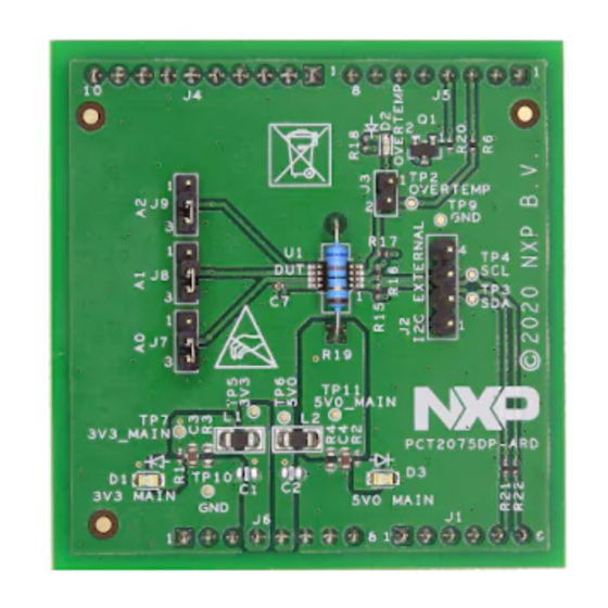
MOS transistor. The IC has a 3-bit address input, allowing a total of 27 distinct addresses. For more details regarding the address setting, see PCT2075DP datasheet (NXP Semiconductors). The jumpers J7 to J9 located on the development board allow the user to set any address specified in the datasheet. - Page 7 UM11580 NXP Semiconductors PCT2075DP-ARD evaluation board Figure 2. PCT2075DP-ARD board, top view Figure 3. PCT2075DP-ARD board, bottom view UM11580 All information provided in this document is subject to legal disclaimers. © NXP B.V. 2021. All rights reserved. User manual Rev. 1.0 — 22 February 2021...
-
Page 8: Arduino Port
A4 / SDA common line for J2 – 5 and J4 – 9. A5 / SCL common line for J2 – 6 and J4 – 10. 4.3 Schematic, board layout and bill of materials The schematic, board layout and bill of materials for the PCT2075DP-ARD evaluation board are available at http://www.nxp.com/PCT2075DP-ARD... -
Page 9: Installing And Configuring Software And Tools
PCT2075DP-ARD evaluation board Installing and configuring software and tools PCT2075DP-ARD evaluation board is designed and built as a daughterboard able to work in conjunction with a motherboard equipped with an Arduino port. The board built to be fully compatible with the following NXP evaluation boards: •... - Page 10 J1 jumper shall be placed in position 5-6. If using an external power supply (connected to J2), the jumper J1 will be placed in position 1-2 2. Insert the PCT2075DP-ARD daughter card on the Arduino port of the EVK (see Figure 3.
-
Page 11: Using Pct2075Dp-Ard With Lpc55S69-Evk Board
PCT2075DP-ARD evaluation board Figure 5. PCT2075DP-ARD daughterboard / IMXXRT1050 EVK board assembly 6.2 Using PCT2075DP-ARD with LPC55S69-EVK board Figure 6 shows the required hardware for operation of the PCT2075DP-ARD and LPC55S69-EVK board. • One LPC55S69-EVK board • One PCT2075DP-ARD daughterboard • One USB-A / USB Micro-B cable •... - Page 12 Figure 6. PCT2075DP-ARD daughterboard and LPC55S69-EVK motherboard To configure the hardware and workstation, complete the following procedure: 1. Insert the PCT2075DP-ARD daughter card to P16 – P19 connectors located on LPC55S69-EVK development board (see the marked pins of P16 – P19, Figure 2.
-
Page 13: Using Pct2075Dp-Ard With 8Mminilpd4-Evk Board
Figure 7. PCT2075DP-ARD daughterboard / LPC55S69-EVK board assembly 6.3 Using PCT2075DP-ARD with 8MMINILPD4-EVK board If 8MMINILPD4-EVK board is used for PCT2075DP-ARD operation, a third board (IMX8MMINI-IARD interposer board) must be used, especially designed and built as EVK – daughterboard interconnection. The 8MMINILPD4-EVK is not equipped with an Arduino port;... - Page 14 PCT2075DP-ARD evaluation board To attach the daughterboard to the EVK, it is necessary to use the IMX8MMINI-IARD interposer boards by plugging PCT2075DP-ARD to the Arduino connector of the interposer, and then the interposer to expansion connector (J1003), located on the i.MX8MMINI EVK board (see...
-
Page 15: Using Pct2075Dp-Ard With Another Arduino Device
IC damage. GUI description A GUI application is available for the three EVK boards from NXP Semiconductors. The application is common for all EVKs / development boards. This section describes the GUI application and how the user can control the PCT2075DP-ARD daughterboard from the graphical interface. - Page 16 I C-bus fails. Choosing a different address than was set on the PCT2075DP-ARD daughterboard, when Connect button is activated a pop-up window with the message: “Unable to Connect with Daughter Card” appears on the screen. Assuming the correct parameters are chosen, clicking the Connect button establishes connection with the EVK.
- Page 17 UM11580 NXP Semiconductors PCT2075DP-ARD evaluation board heater status is sent to the daughterboard when Set button (located on the right / bottom side of the section) is clicked. After the connection is established, the current value of temperature measured by the sensor is displayed in the upper blue region (marked with the red arrow).
- Page 18 OS indicator shows the logic level of Overtemp Shutdown (OS) output of the DUT IC. The indicator replicates the status of the on-board LED (D2) located on PCT2075DP-ARD daughterboard. UM11580 All information provided in this document is subject to legal disclaimers.
- Page 19 UM11580 NXP Semiconductors PCT2075DP-ARD evaluation board Figure 13. Graphical interface – “Device Control” / “Tidle Registers” tab activated 13) is Tidle registers. This parameter refers to sampling The last secondary tab (Figure period of temperature measurement feature. Since the temperature variations are generally slow, the DUT IC offers to set the time between measurements, keeping the IC idle between measurements to save power.
-
Page 20: Abbreviations
UM11580 NXP Semiconductors PCT2075DP-ARD evaluation board read, and displayed on the GUI. For details regarding the register map, see PCT2075 datasheet. Abbreviations Table 2. Abbreviations Acronym Description Device Under Test Electro Static Discharge Evaluation Board Graphical User Interface C-bus Inter-Integrated Circuit bus... -
Page 21: Legal Information
10.1 Definitions and products using NXP Semiconductors products in order to avoid a default of the applications and the products or of the application or use by customer’s third party customer(s). NXP does not accept any liability in this Draft —... - Page 22 Pin chart of Arduino connectors and their Tab. 2. Abbreviations ...........20 usage ..............8 Figures Fig. 1. PCT2075DP-ARD board layout (top view) ..6 Fig. 9. PCT2075DP-ARD daughterboard / Fig. 2. PCT2075DP-ARD board, top view ....7 8MMINILPD4-EVK board operation ....15 Fig.
-
Page 23: Table Of Contents
Kit contents ............4 Assumptions ............5 Static handling requirements ......5 Minimum system requirements ......5 Getting to know the hardware ......5 PCT2075DP-ARD features ........ 5 Kit featured components ........5 4.2.1 Board layout and component placement ... 6 4.2.2 Arduino port ............8 Schematic, board layout and bill of materials ............
Need help?
Do you have a question about the PCT2075DP-ARD and is the answer not in the manual?
Questions and answers