Table of Contents
Advertisement
Quick Links
Advertisement
Table of Contents

Related Manuals for NXP Semiconductors PCA9420UK-EVM


Summary of Contents for NXP Semiconductors PCA9420UK-EVM
- Page 1 UM11216 PCA9420UK-EVM evaluation board user manual Rev. 1.2 — 11 March 2020 User manual Document information Information Content Keywords PCA9420UK-EVM evaluation board Abstract This user manual provides guidelines on how to use the PCA9420-EVM evaluation board...
- Page 2 UM11216 NXP Semiconductors PCA9420UK-EVM evaluation board user manual Revision history Revision history Date Description v.1.2 20200311 Added Section 15; removed references to PCA9420BS v.1.1 20191016 Updated Figure Figure Section 10 20190718 Initial version UM11216 All information provided in this document is subject to legal disclaimers.
-
Page 3: Pca9420Uk-Evm (Wlcsp) Evaluation Board
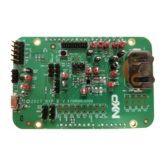
UM11216 NXP Semiconductors PCA9420UK-EVM evaluation board user manual PCA9420UK-EVM (WLCSP) Evaluation Board Figure 1. PCA9420UK-EVM evaluation board UM11216 All information provided in this document is subject to legal disclaimers. © NXP B.V. 2020. All rights reserved. User manual Rev. 1.2 — 11 March 2020... -
Page 4: Kit Contents/Packing List
NXP Semiconductors PCA9420UK-EVM evaluation board user manual Kit contents/packing list The kit contents include: • Assembled and tested PCA9420UK-EVM evaluation board in an anti-static bag • USB to MPSSE Serial cable for I C communication • USB 2.0 Cable • Spare jumpers UM11216 All information provided in this document is subject to legal disclaimers. -
Page 5: Required Equipment
UM11216 NXP Semiconductors PCA9420UK-EVM evaluation board user manual Required equipment To use this kit, the equipment needed is: • 1-cell Li-ion Battery • 5.0V power supply or USB with enough current capability (1.5A or above for maximum performance) • PCA9420 GUI installed on a Windows PC •... -
Page 6: Device Description
UM11216 NXP Semiconductors PCA9420UK-EVM evaluation board user manual Device description The PCA9420UK is a highly-integrated Power Management IC (PMIC), targeted to provide a full power management solution for low power microcontroller applications or other similar applications. The device consists of a linear battery charger capable of charging up to 315 mA current. -
Page 7: Key Features
UM11216 NXP Semiconductors PCA9420UK-EVM evaluation board user manual Key features • Linear battery charger for charging single cell li-ion battery • 20V tolerance on VIN pin • Programmable input OVP (5.5V or 6V) • Programmable constant current (up to 315 mA) and pre-charge low voltage current threshold •... -
Page 8: Board Description
UM11216 NXP Semiconductors PCA9420UK-EVM evaluation board user manual Board description Figure 2 describes the main elements on the board. Figure 2. PCA9420UK-EVM board description Table 1. Board description Number Name Description USB Input USB power supply for the PCA9420UK Logic pin for Logic high or low for MODESEL1&2 pins... - Page 9 UM11216 NXP Semiconductors PCA9420UK-EVM evaluation board user manual Number Name Description PMIC-OUT All regulators’ output Button connected to ON pin I2C-PU Logic voltage selection for I MODE-PU Logic voltage selection for MODESEL0&1 function FTDI-CTRL C interface Input selection for an external LDO between VBAT and...
-
Page 10: Jumper And Switch Definitions
Jumper and switch definitions Figure 3 shows the location of jumpers and switch on the evaluation board. Figure 3. Jumper and switch locations for PCA9420UK-EVM Table 2 describes the function and settings for each jumper and switch. Table 2. Jumper and switch definitions... - Page 11 UM11216 NXP Semiconductors PCA9420UK-EVM evaluation board user manual Jumper/ Description Setting Connection/Result Switch [1-2] Pullup to external LDO output Pullup configuration for MODE function [2-3] Pullup to LDO2 output [1-2] Logic high Logic configuration for MODESEL1 [2-3] Logic low [1-2]...
-
Page 12: Evaluation Board Connections
UM11216 NXP Semiconductors PCA9420UK-EVM evaluation board user manual Evaluation board connections Figure 4. PCA9420UK-EVM connection 8.1 Connections Connect wires on the following pins as shown in Figure 4, and make sure the power supply is turned off during the wiring stage: •... -
Page 13: Pca9420 Gui Software Installation
UM11216 NXP Semiconductors PCA9420UK-EVM evaluation board user manual PCA9420 GUI Software Installation • Unzip the provided PCA9420 Evaluation Kit GUI installation execution file, follow the step by step instruction on the screen. • During the installation process, the FTDI interface cable driver will also be installed, please refer to the screen capture for the reference. -
Page 14: Gui Panels
PCA9420UK-EVM evaluation board user manual Figure 6. GUI overview 9.1 GUI panels When the GUI is launched, it looks for a PCA9420UK-EVM target board connected via the USB cable. If connected, the GUI panels display “Connected” on the bottom left. UM11216 All information provided in this document is subject to legal disclaimers. -
Page 15: The Gui Quick Guide
UM11216 NXP Semiconductors PCA9420UK-EVM evaluation board user manual 10 The GUI Quick Guide As shown in Figure 7, the GUI is a user-friendly tool which allows access to the on-chip registers to perform write/read commands manually or automatically (depending on GUI setting). - Page 16 UM11216 NXP Semiconductors PCA9420UK-EVM evaluation board user manual the case multiple interrupts bits are set at the same time, the button clears all set interrupts bits. 9. Connections Status: When valid communication between GUI and the hardware is established, it shows “connected”, otherwise it shows “disconnected”. The cable used is also shown at the right side of the connection status bar.
-
Page 17: Evaluation Board Schematic
UM11216 NXP Semiconductors PCA9420UK-EVM evaluation board user manual 11 Evaluation Board Schematic J1_INT_B J4_INT_B aaa-033573 Figure 8. PCA9420UK-EVM (WLCSP) evaluation board UM11216 All information provided in this document is subject to legal disclaimers. © NXP B.V. 2020. All rights reserved. User manual Rev. -
Page 18: Evaluation Board Bom List
UM11216 NXP Semiconductors PCA9420UK-EVM evaluation board user manual 12 Evaluation Board BOM List Table 3. Bill of Materials (BOM) Size Description Manufacture Part Number Notes (inch) CAP CER 0.1µF 50V 10% X7R 0402 MURATA GRM155R71H104KE14D C3, C10, C17, CAP CER 1.0µF 16V 10% X7R... - Page 19 UM11216 NXP Semiconductors PCA9420UK-EVM evaluation board user manual Size Description Manufacture Part Number Notes (inch) HDR 1X10 TH 100MIL CTR 338H SAMTEC TSW-110-07-F-S AU 100L HDR 1X8 TH 100MIL SP 338H J1, J3 SAMTEC TSW-108-07-F-S AU 100L WURTH ELEKTR CON 5 USB MICRO_...
-
Page 20: Placement
UM11216 NXP Semiconductors PCA9420UK-EVM evaluation board user manual 13 Placement Figure 9. PCA9420UK-EVM Evaluation Board Placement UM11216 All information provided in this document is subject to legal disclaimers. © NXP B.V. 2020. All rights reserved. User manual Rev. 1.2 — 11 March 2020... -
Page 21: Layout Guideline
UM11216 NXP Semiconductors PCA9420UK-EVM evaluation board user manual 14 Layout Guideline The following guidelines for PCA9420UK are arranged from most critical to least critical priority: • Place ASYS input capacitor (C2) as close to ASYS and PGND as possible. • Place VBAT input capacitor (C3) as close to VBAT and PGND as possible. The input capacitor delivers a high di/dt current pulse when the high-side MOSFET turns on. -
Page 22: Orderable Part Number
UM11216 NXP Semiconductors PCA9420UK-EVM evaluation board user manual 15 Orderable part number • PCA9420UK-EVM UM11216 All information provided in this document is subject to legal disclaimers. © NXP B.V. 2020. All rights reserved. User manual Rev. 1.2 — 11 March 2020... -
Page 23: Legal Information
Customer is responsible for doing all necessary testing for the customer’s applications and products using NXP Semiconductors products in order to avoid a 16.2 Disclaimers default of the applications and the products or of the application or use by customer’s third party customer(s). - Page 24 UM11216 NXP Semiconductors PCA9420UK-EVM evaluation board user manual Tables Tab. 1. Board description ..........8 Tab. 3. Bill of Materials (BOM) ........18 Tab. 2. Jumper and switch definitions ......10 UM11216 All information provided in this document is subject to legal disclaimers.
- Page 25 UM11216 NXP Semiconductors PCA9420UK-EVM evaluation board user manual Figures Fig. 1. PCA9420UK-EVM evaluation board ....3 Fig. 6. GUI overview ...........14 Fig. 2. PCA9420UK-EVM board description ....8 Fig. 7. GUI summary ..........15 Fig. 3. Jumper switch locations Fig. 8. PCA9420UK-EVM...
-
Page 26: Table Of Contents
UM11216 NXP Semiconductors PCA9420UK-EVM evaluation board user manual Contents PCA9420UK-EVM (WLCSP) Evaluation Board ..............3 Kit contents/packing list ........4 Required equipment ........... 5 Device description ..........6 Key features ............7 Board description ..........8 Jumper and switch definitions ......10 Evaluation board connections ......
Need help?
Do you have a question about the PCA9420UK-EVM and is the answer not in the manual?
Questions and answers