Table of Contents
Advertisement
Quick Links
Advertisement
Table of Contents

Subscribe to Our Youtube Channel
Related Manuals for ELC ALR3220


Summary of Contents for ELC ALR3220
- Page 1 USER MANUAL 0 – 32 V ; 0 – 20 A ALR3220 DC PROGRAMMABLE STABILIZED POWER SUPPLY...
-
Page 2: Table Of Contents
SYNOPSIS PREFACE ..........................3 DESCRIPTION ........................3 PRESENTATION ........................3 FUNCTIONAL DESCRIPTION OF THE UNIT ................. 3 SAFETY INSTRUCTIONS ...................... 4 SAFETY TERMS AND SYMBOLS ..................4 PACKAGING AND REPACKAGING ..................4 OPERATING.......................... 5 TECHNICAL FEATURES ....................... 5 OVERVIEW ........................... 8 FRONT PANEL ........................ -
Page 3: Preface
2 DESCRIPTION 2.1 PRESENTATION You just bought a DUAL DC STABILIZED PROGRAMMABLE POWER SUPPLY type elc ALR3220. We thank you and congratulate you for your good choice. elc's company is a specialist manufacturer proposes a wide range of POWER SUPPLIES and many other electronic test instruments : FUNCTION GENERATORS, DECADE BOXES, DIGITAL PANEL METERS... -
Page 4: Safety Instructions
PROTECTIVE GROUND (EARTH) TERMINAL TO MANUEL RISK 2.5 PACKAGING AND REPACKAGING Your power supply ALR3220 comes with an quickstart guide and its power cable 2 poles + earth type "EUROPE" : CEE7 / 7 - IEC60320 C13. ENGLISH 4000 4 356_03-21... -
Page 5: Operating
3 OPERATING 3.1 TECHNICAL FEATURES The specifications below are given after at least 30 minutes use within the specified operating temperature range. Constant voltage Automatic Operating Constant current Automatic Voltage 0 to 32.00 Volts (0 to ±10mV) Current 0 to 20.00 Amps Mini maxi adjustment OVP (voltage protection) 0 to 32.20 Volts... - Page 6 3.1.1 Connections Front panel Safety terminals Ø4 mm Outputs + and - Rear panel Screw terminal block for 2,5mm² Front panel Safety terminals Ø4 mm Ground terminal Rear panel Earth and safety terminal Ø4 mm 3.1.2 Display Display LCD graphic display FSTN N&B 3.2 inch Resolution 128 x 64 pixels Backlight...
- Page 7 3.1.9 Other caracteristics 220 – 240 Volts ±10%, 50 – 60 Hz Power source EEC socket C14 for cable 2 poles + earth C13 (2P + E) Maximum power consumption 770W (2.1W in Standby mode) Internal fuses (x2) AC input 5 x 20 ;...
-
Page 8: Overview
4 OVERVIEW FRONT PANEL LCD display Keypad double function Functions key ON/OFF general Keys setting Standby Safety socket output Earth socket ENGLISH 4000 4 356_03-21... -
Page 9: Rear Panel
REAR PANEL Handel RS232 connector RS485 connector Sense connector Powerful connector Analogical control connector USB Connector AC power inlet socket Power AC switch Earth safety socket Ø4mm Cord storage ENGLISH 4000 4 356_03-21... -
Page 10: Short Description Of The Front Panel
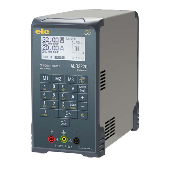
5 SHORT DESCRIPTION OF THE FRONT PANEL 5.1 DISPLAY The basic mode on the LCD display (1) shows the value of the voltage and current setting, the output's powerful, the currently regulation mode (CV or CC) and the output's state (ON or OFF). If the OVP and OCP stopped are less than the maximum setting (32V and 20A) they will be displayed. -
Page 11: Description Of Control Commands
6 DESCRIPTION OF CONTROL COMMANDS 6.1 PARAMETERS SETTING 6.1.1 Escape Key Allow to go out without taking the value. If no action, allow access secondary function. Touch 6.1.2 Setting Voltage and Current Two possibilities : Action Description Select the voltage or current value to change Touch on Enter the value Touch on... - Page 12 Action Description Select key “2 ” Touch on Enter the U (OVP) or I (OCP) limit Touch on Enter the value Touch Valid the value Touch CANCEL OVP or OCP Select key “2 ” Touch on Enter the U (OVP) or I (OCP) you need to cancel Touch on Cancel the limit selected...
-
Page 13: Memories
6.2 MEMORIES 6.2.1 Storage setting Action Description Select key “2 ” Touch on Select the function “Storage” configuration Touch on Select where to save the current configuration Touch on (1-15). The display shows the registration number and the current contents. touch on Stores the current configuration in the storage number selected. -
Page 14: Control 0-10V
Action Description Touch on Recall configuration number 1, 2 or 3. Touch on Recall the configuration with the output disconnected Touch on 6.3 CONTROL 0-10V This function allows changing the set values by an analogical voltage or a potentiometer or a variable resistor (see wiring Appendix E). The maximum setpoint is the one displayed before activating the function. -
Page 15: Control Remote Sensing
Set the voltage and current supply according to your use. o Go to the "sense" menu "AUTO" on the ALR3220. o Make the short circuit with your two cords (instead of the load) o Validate o The sense is active. -
Page 16: Control Utilities
4 wires mode: (see wiring Appendix G) The output is at the back of the terminal block, the maximum compensation of the voltage drop is equal to : 32V – V instruction. (example : 12V maximum for 20V nominal). 6.5 CONTROL UTILITIES This command control includes the following functions : - Language choice - Changing the contrast of the display. -
Page 17: Configuration Of Rs232 & Rs485 Interfaces
Action Description Select key “2 ” Touch on Select the function “Util” Touch on Select "LINK" mode Touch on The power supply on which the command is triggered takes control of the 2nd power supply. Touch on Valid the choice with “OK” Touch on CONFIGURATION OF RS232 &... -
Page 18: Programmed Functions
6.7 PROGRAMMED FUNCTIONS Enabling this key allows to get to the output, multiple periodic wave forms or not, in voltage or current mode (see Appendix H). Action Description Select the key “2 ” Touch on Select the function generator, “F(t)” Touch on Valid the choice with “OK”... -
Page 19: Pc Control
Action Description LOCKED / UNLOCKED Active the locked or unlocked keyboard Touch on during 4s Action Description Select the key “2 ” Touch on Active the locked "RMT" or unlocked keyboard. (control via USB or RS485) Touch on 6.8.3 Locked setting value Locked setting voltage value Action Description... -
Page 20: Maintenance
Fan doesn’t work 9 AFTER SALE SERVICE The after sales service is ensured by the elc company. During two years, spare parts and workmanship are guaranteed. This guarantee does not apply to instruments presenting defects or faults caused by an improper use (wrong mains voltage, shocks ...) or which have been repaired outside our factory or... -
Page 21: Declaration Of Conformity
59 avenue des Romains 74000 Annecy France Declares the product Name DC POWER SUPPLY Type ALR3220 conformable to the requirements of the directives: Low voltage 2014/35/UE, Electromagnetic Compatibility 2014/30/UE and RoHs 2017/2102/UE. The following harmonized standards have been applied :... -
Page 22: Appendix A - Operating Codes
APPENDIX A – OPERATING CODES Commands control format : [address] <SP>Parameter<SP>Command<SP>[Value]<CR> [address] = character ASCII 0 (port USB – port RS232) character ASCII 0 to 31 (port RS485) character ASCII 32 (broadcast address) Parameter = VOLT – CURR – OVP – OCP – OUT – RCL – STO – REM – IDN – SENSE –... - Page 23 Command & Answers Description Command : Writing the current setpoint in mA. [Address] CURR WR [0-20500] Answer : [Address] OK Command : Writing the limit voltage setpoint in mV. [Address] OVP WR [0-32200] Answer : [Address] OK Command : Writing the limit current setpoint (mA) channel 1, ...
- Page 24 Command & Answers Description Command : Reading the limit voltage setpoint in mV. [Address] OVP RD Answer : [Address] OK [0-32100] Command : Reading the limit current setpoint in en mA. [Address] OCP RD Answer : [Address] OK [0-20450] Command : Reading the output connection.
- Page 25 Command : Reading the device ID. [Address] IDN RD Answer : [Address] OK ALR3220 VERSION [N] Command : 0 => Change SENSE mode in ‘NONE’ 1 => Change SENSE mode in ‘4 WIRES’ [Address] SENSE WR [0-1] Answer : ...
-
Page 26: Appendix B -Usb Connection
A / B type USB (its length shouldn’t exceed 5 meters). Install the file. Your PC is ready to communicate with the ALR3220. Use "Hyper Terminal ®" simple utility to communicate via the serial port, present on all PCs with Windows 95®, 98®, XP®, Seven®. -
Page 27: Appendix D - Rs485 Connection
APPENDIX D – RS485 CONNECTION You will find on the website www.elc.fr, LabVIEW ® drivers to drive the master. APPENDIX E – 0–10V CONNECTION This function changes the voltage setpoints for channels 1 and 2 or voltage / current for channel 1 via an analogical voltage, a potentiometer or resistance. -
Page 28: Appendix F - On/Off External Control
APPENDIX F – ON/OFF EXTERNAL CONTROL Use pin ON/OFF to GND (relay contact, manual switch, sensor, ..) allow control isolation of output . Open contact => ON output, Closed contact => OFF output. Connection input control APPENDIX G – SENSE 4 WIRES Configuration "sense"... -
Page 29: Appendix H - Sequencer
APPENDIX H – SEQUENCER The key allows to generate the signal function (Voltage or Current) on output. Step Action Description Before entering the sequencer, initialize the setpoints that will be taken as reference values to generate the signal. Select key “2 ”... - Page 30 Step Action Description Valid timer value, sequencer run, for exemple : Touch on Setting arbitrary multi-shot signal Select key “2 ” Touch on Select sequencer function Touch on Enter in setup sequencer mode Touch on Select multi-shot arbitrary signal. Touch on Select regulation mode (voltage or current) Touch on Select range of timer : seconds or minutes...
- Page 31 Step Action Description Enter number of repeat signal (1 to 99). Touch on Run sequencer with the key "OK" Touch on Displaying at right up repeat value remaining Step Action Description Setting arbitrary periodic signal. Select key “2 ” Touch on Select sequencer function Touch on Enter in setup sequencer mode...
- Page 32 Step Action Description Run sequencer with the key "OK" Touch on ENGLISH 4000 4 356_03-21...
- Page 33 Setting example pulse I = 4A R load = 2,25 Ω Function : square Regulation mode : current Unity : seconde Ton : 0.1s Toff :10 s Display after setting the square signal Measurement results on 2.25 Ω resistive load: 100ms impulse ever 10s ..
-
Page 34: Appendix I - Serial, Symmetric Or Parrallel Mode
APPENDIX I – SERIAL, SYMMETRIC or PARRALLEL MODE Link (Linking of two power supplies) Wire the RS485 as follows : Master Slave MASTER SLAVE G N D Mode of setting : Master Slave The master power supply sends the information to the slave. By linking together the two "+"...
Need help?
Do you have a question about the ALR3220 and is the answer not in the manual?
Questions and answers