Table of Contents
Advertisement
Advertisement
Table of Contents

Related Manuals for LELY Attis PT 130


Summary of Contents for LELY Attis PT 130
- Page 1 Lely Attis PT 130 Operator Manual W-H003.1403EN English Original...
- Page 3 Orbiter, Quaress, Qwes, SAE, Shuttle, Splendimo, Storm, T4C, Tigo, Viseo, Vector, Voyager, Walkway and Welger are registered trademarks of the Lely Group. The right of exclusive use belongs to the companies of the Lely Group. All rights reserved. The information given in this publication is provided for information purposes only and does not constitute an offer for sale.
- Page 4 Trademarks, copyright and disclaimer...
- Page 5 Study and understand this information thoroughly before you operate the Lely Attis. Failure to do so could result in personal injury or damage to equipment. Please consult your local Lely service provider if you do not understand the information in this manual, or if you need additional information.
- Page 6 Always include the type and serial numbers of your product when you contact your local Lely service provider or order spare parts. We suggest you to complete the table below with the type and serial numbers of your product. This makes sure you can easily find the information.
- Page 7 Abbreviations This manual uses the following abbreviations: • HCP = Hydraulic Control Panel • LCD = Liquid Crystal Display • N/A = Not applicable • P = Oil flows to the cylinders • PT = Pulled Turntable • T = Oil flow returns to the tank Preface...
- Page 8 Preface...
-
Page 9: Table Of Contents
Table of Contents Introduction............................1-1 Optional extras......................... 1-3 1.1.1 Extension kit for 500 mm film....................1-3 1.1.2 Safety towing chain........................1-4 1.1.3 Suction cup..........................1-5 1.1.4 Flow control unit........................1-6 1.1.5 Battery extension cable set......................1-7 1.1.6 Bale end-tipper.........................1-8 1.1.7 Foot plate..........................1-9 Safety..............................2-1 Signal words..........................2-1 Safety instructions........................2-1 2.2.1 Safety instructions........................2-1... - Page 10 Rotation speed too high......................6-1 Diagrams and tables.......................... 7-1 Bolt and nut torque table......................7-1 Hydraulic diagram........................7-2 Quick referencecharts......................7-4 7.3.1 Default menu..........................7-4 7.3.2 CAL.2 menu..........................7-5 7.3.3 CAL.3 menu..........................7-6 Specifications............................. 8-1 Attis PT 130 Specifications...................... 8-1 Table of Contents...
-
Page 11: Introduction
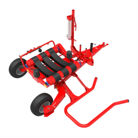
INTRODUCTION The Lely Attis PT 130 is a trailed bale wrapper to load and wrap cylindrical forage bales in a plastic stretch film. The loading arm picks the forage bale up from the ground and moves it to the wrapping table. - Page 12 1. Film cutter - 2. Film clip - 3. Film clamp - 4. Wrapping table - 5. Film holder - 6. Film dispenser - 7 Hydraulic system - 8. Parking jack - 9. Control panel -10. Pull eye - 11. Film roll storage - 12.
-
Page 13: Optional Extras
Optional extras 1.1.1 Extension kit for 500 mm film This extension kit changes the rotation speed of the wrapping table rollers to handle film rolls with a width of 500 mm. The extension kit consists of a gear wheel and a drive chain extension. The gear wheel is replaced with the standard gear wheel to change the rotation speed of the wrapping table rollers for correct overlap of the film layers. -
Page 14: Safety Towing Chain
1.1.2 Safety towing chain The safety towing chain prevents separation between the towed vehicle and the towing vehicle, if the towing device breaks. Install the safety towing chain to the eye bracket on the drawbar (Figure 4, page 1‑4), attach the hook of the safety towing chain to the tractor, and shorten the length of the chain in such a way, that the drawbar cannot touch the ground in case the towing device breaks. -
Page 15: Suction Cup
1.1.3 Suction cup The suction cup mount assembly can be attached to any non-porous surface. The suction pad holds the assembly against the surface based on vacuum. The crank lever creates a vacuum to hold or loosen the mounting position. The bracket is used to mount the E‑link manual controller. 1. -
Page 16: Flow Control Unit
1.1.4 Flow control unit The flow control unit controls the hydraulic oil flow into the hydraulic system. The black knob on the unit is a throttle valve to regulate the oil flow. 1. Adjusting knob - +. Open - -. Close Figure 6. -
Page 17: Battery Extension Cable Set
1.1.5 Battery extension cable set The battery cable set is an extension cable to connect the E‑link to the battery. 1. E‑link Plus manual controller - 2. Battery cable set - 3. Fuse (30A) Figure 7. Battery cable set Introduction... -
Page 18: Bale End-Tipper
1.1.6 Bale end-tipper The bale end-tripper sets the bale on its end during unloading. This makes sure the bale cannot roll away on sloping terrain and minimises damage to the wrapped bale since the ends have more film. 1. Bale end tipper Figure 8. -
Page 19: Foot Plate
1.1.7 Foot plate The foot plate prevents the bale end-tipper (page 1‑8) frame to sink into the muddy, peaty and wet soils, so the bale end-tipper can work properly to tip the bale. 1. Foot plate Figure 9. Foot plate Introduction... - Page 20 1-10 Introduction...
-
Page 21: Safety
SAFETY This chapter contains safety instructions you must obey when you use or do maintenance on your Lely Attis. It also explains the safety decals on the Lely Attis. Signal words Note the use of the signal words DANGER, WARNING and CAUTION. The... -
Page 22: Hydraulic Safety Instructions
As a hydraulic cylinder is kept open by the accumulator pressure it will be necessary to release this before removing the accumulator or working on the hydraulic cylinder. Otherwise injury may occur. This procedure must be done by an authorized Lely service mechanic. • All hydraulic hoses must be replaced every 5 years. -
Page 23: Explanation Of The Safety Decals
Explanation of the safety decals Caution: Read manual Read the operator's manual carefully before you operate the Attis Danger: Moving parts Keep away from all moving parts unless they are locked and cannot move. Danger: Turning parts Keep away from all turning parts unless they are locked and cannot move. -
Page 24: Explanation Of Remaining Decals
Danger: Risk of being crushed Do not sit on the Attis. Explanation of remaining decals Note: Grease point This indicates a grease point, read the operator manual for maintenance instructions. Note: Instruction This indicates how to form the film into the film stretcher. -
Page 25: Position Of The Decals
Position of the decals Figure 10. Positions of decals Safety... -
Page 26: Explanation Of The Operation Instructions
Explanation of the operation instructions In this manual the tables with operation instructions are used. These instruction tables must be read from left to right and from top to bottom. The tables have three columns: • the left column contains: •... - Page 27 hold Next instruction Last instruction. Safety...
- Page 28 Safety...
-
Page 29: Operation
OPERATION Hydraulic control panel Read the tractor manual for the correct procedures to operate the tractor Note: hydraulics. The operator switches the handle(s) or moves the joystick to operate the Attis. The following positions of the switches or joystick enable an action to the hydraulic system: •... - Page 30 The hydraulic systems (forward/reverse) marked on the front of the drawbar CAUTION are depending on how the connections are made to the tractor. Hydraulic system (I): The hydraulic system (I) is controlled by the E‑Link manual controller to operate the following functions: the rotation of the wrapping table.
-
Page 31: E-Link Manual Controller
The E-link Basic Manual Controller has a LCD display, four switches, five buttons and an emergency stop that enable the user to give commands and change values in the Lely Attis.The LCD display also shows reports and alarms. Figure 13. E-Link Basic manual controller... - Page 32 The E-Link manual controller has the following buttons: Number Button/ Auto Function Manual Function switch Emergency stop Display Adds one rotation to the total number of rotations or pauses the counting of rotations. Set/reset button. Enter a number in Cal mode or resets the field bale count and bales per hour.
-
Page 33: Interface Structure
Lower the loading arm (down) 3.2.1 Interface structure The display on the E-Link Basic manual controller has six different screens. The buttons helps you to navigate through the screens. After approximately five seconds the E-link resets to default screen (screen 1). -
Page 34: Start Up Screens
The second calibration menu (CAL.2) (page 3‑9) and the third calibration menu (CAL.3) (page 3‑11) are only applicable for Lely personnel and service engineers. The screens of the menus are used to change the settings and the behaviour of the Attis. - Page 35 • incorrect, go to step 2. • correct, save both digits and return to the default screen (page 3‑6). release 3.2.3.2 TOTAL # (screen 2) A / 0000 The Totals screen shows the value of one of the eight pre-selected fields ◄...
- Page 36 Reset the average total of the wrapped bale to 0 Hold 5 sec. 3.2.3.6 RPM/min. (Screen 6) The RPM/min. screen shows the current speed of revolution of the wrapping ◄ ▼ table at intervals of three seconds in the range of 0...99 r.p.m. Select the speed value Activate this menu to define the speed.
-
Page 37: Second Calibration Menu (Cal.2)
3.2.4 Second calibration menu (CAL.2) The second calibration menu (CAL.2) can be activated by the following steps: Turn off the E-link Basic push Activate the calibration menu 1x + hold Turn on the E-link release Proceed the next step within 5 seconds wait <... - Page 38 3.2.4.4 Set delay time to hold the film knife (screen 2.4) The Grand Total screen shows the delay in seconds to hold the film knife ◄ ▼ closed, after the number of pulses has been counted (page 3‑9). The value range is 0.0...9.9 and the default is 0.5 seconds.
-
Page 39: Third Calibration Menu (Cal.3)
3.2.5 Third calibration menu (CAL.3) The third calibration menu (CAL.3) can be activated by the following steps: Turn off the E-link Basic push Activate the calibration menu 1x + hold Turn on the E-link release Proceed the next step after 5 seconds wait >... -
Page 40: Connect To The Tractor
Connect to the tractor Preparations WARNING Adjust the height of drawbar pull eye. (Figure 24, page 4‑ • Prepare the installation of the E-link Basic manual controller • in the tractor cabine: Install the E-Link Basic manual controller in the tractor. If applicable, use the suction cup (page 1‑5). -
Page 41: Disconnect The Attis From The Tractor
Disconnect the Attis from the tractor Always position the tractor on solid ground before you disconnect the WARNING Attis from the tractor. Make sure there are no persons near the Attis when you disconnect it from the tractor. Always switch off the tractor engine and remove the ignition key before you leave the tractor cab. -
Page 42: Move The Attis To The Transport Position
Move the Attis to the transport position Make sure there are no persons in the area when you move the Attis to WARNING the transport position. Use all lights and warning signals as defined by your local road traffic CAUTION regulations. - Page 43 1. R-Clip - 2. Locking pin A. Transport position - B = Working position Figure 15. Lock/unlock the loading arm Operation 3-15...
- Page 44 1. Locking pin - 2. R-clip - 3.Transport wheel A. Operating force to lift the transport wheel from the ground B. Play to rotate the transport wheel C. Working position D. Transport position Figure 16. Lift and rotate the transport wheel 3-16 Operation...
- Page 45 1. Lynch pin - 2. Bracket A = Working position - B. Transport position Figure 17. Working/transport position bale end-tipper Operation 3-17...
-
Page 46: Move The Attis To The Working Position
Move the Attis to the working position Make sure there are no persons in the area when you move the Attis to WARNING the working position. Procedure Remove the transport lock pin from the working position hole. Install the transport lock pin into the transport position hole Switch on the E-link manual controller. -
Page 47: Move The Attis To The Maintenance Position
Move the Attis to the maintenance position Make sure there are no persons in the area when you move the Attis to WARNING the maintenance position. Procedure Stop driving the tractor. Lift the wrapping table to the top position. Switch off the E‑link manual controller. Switch off the tractor. -
Page 48: Process Overview
Process overview This section describes the Attis behaviour in automatic mode. The operator can interact with several functions during wrapping. 3.8..1 Loading The operator operates the loading arm to the ground position and drives to the bale. The bale have to be loaded in the loading arm till the end of the load arm. -
Page 49: Start Wrapping
Start wrapping Procedure Pull the foil from the film roll and tie the foil to the eye bracket on the frame (Figure 19, page 3‑21). Verify the setting of the adjustments before wrapping and after replacement or maintenance to the Attis: •... -
Page 50: Auto Mode
3.9.1 Auto mode Make sure no persons are within a 10 m (11 yd) radius of the Attis WARNING during operation. Do not operate the machine on a terrain with a slope of more than than 8°. A load on the wrapping table or loading arm of the Attis may influence the CAUTION maneuverability of the tractor. - Page 51 11. Move the wrapping table to the top position until it stops, while the film is cut and the bale is unloaded to the ground. hold up 12. Move the wrapping table to the bottom position. When the wrapping table has reached the bottom position, it turns automatically to the loading position to receive the next down bale.
- Page 52 Figure 21. Unload and tip a bale on its end 3-24 Operation...
- Page 53 Figure 22. Unload a bale Operation 3-25...
-
Page 54: Manual Mode
3.9.2 Manual mode Make sure no persons are within a 10 m (11 yd) radius of the Attis WARNING during operation. Do not operate the machine on a terrain with a slope of more than than 8°. A load on the wrapping table or loading arm of the Attis may influence the CAUTION maneuverability of the tractor. - Page 55 Close the film cutter Closes the film cutter. Lift the wrapping table Lift the wrapping table. Lower the wrapping table Lower the wrapping table. Operation 3-27...
-
Page 56: Replace A Film Roll
3.10 Replace a film roll Procedure Stop the tractor engine and remove the ignition key from the tractor WARNING before you do maintenance or adjustments to the Attis. Move the the lock of the dispenser downwards to engage the lock. Pull the dispenser backwards to release the dispenser from the film roll. - Page 57 I. Remove - II. Install - 1. Dispenser lock - 2. Dispenser - 3. Film lock handle - 4. Film holder - 5. Film roll - 6. Instruction sticker Figure 23. Replace a film roll Operation 3-29...
-
Page 58: Stop Wrapping
3.11 Stop wrapping Procedure Stop driving the tractor. Switch off the E-link manual controller. Put the hydraulic system in the tractor (system I) in neutral. Wait for all moving parts of the Attis to stop. WARNING Switch off the tractor engine Disconnect the E-Link Plus manual controller. -
Page 59: Operation Adjustments
OPERATION ADJUSTMENTS Make sure that the PTO shaft is disengaged and the tractor engine is WARNING switched off before adjustments are made. Adjust the height of the drawbar pull eye Always stop the tractor engine, remove the ignition key and wait until WARNING all moving parts have stopped. -
Page 60: Adjust The Film Holder For Other Film Roll Sizes
Adjust the film holder for other film roll sizes Procedure Adjust the position of the film holder: Remove the two bolts from the film holder. Move the film holder to the applicable position. • Position A is used for 750 mm film rolls. •... - Page 61 A. 750 mm film rolls - B. 500 mm film rolls Figure 25. Adjust the position of the film holder 1. Gearwheel - 2. Chain (incl. 3. Master link) Figure 26. Extension kit for 500 mm film Operation adjustments...
-
Page 62: Adjust The Bearings Adjusting Plate
Adjust the bearings adjusting plate Procedure Release the fasteners of the adjusting plate and bearings at the right side of the Attis. Rotate the adjusting plates to the required size (A, B or C) for the correct tension on the wrapping strings. Make sure the adjustment keep the wrapping rollers parallel to each other. -
Page 63: Adjust The Film Stretch
Adjust the film stretch Procedure 1 If you have an Attis model with two bolts on the gearbox cover: Remove the gear wheel cover. Release the bolts at the top and the bottom of the roller with the smallest gear wheel. Change the two smallest gear wheels (1 and 2) from position: •... - Page 64 Procedure 2 If you have an Attis model with three bolts on the gearbox cover: Remove the gear wheel cover. Release the gear bolt on the gear wheel cover. Release the gears (4 and 5) from the gear wheel cover. Change gear wheels 7 and 8 with 4 and 5: •...
-
Page 65: Adjust The Bale End-Tipper
Adjust the bale end-tipper Procedure: Verify if the bale end-tripper is level in the working position: Use a levelling instrument (2) to level the bale end tipper. If not, then tighten or loosen the nut (1), the tension on the spring, till the bale end-tripper is level in the working position. -
Page 66: Program Settings
Program Settings 4.6.1 Determine the number of wraps Procedure Set the machine in manual mode. 00.00 ◄ ▼ Verify if the machine is set in manual mode. Load a bale on the loading arm Load the bale on the wrapping table in manual mode. Lower the loading arm. - Page 67 10. Close the film cutter to cut the film 11. Un load the bale to the ground 12. Lower the wrapping table back to the horizontal position down 12. Turn the wrapping table in the loading position down 13. Verify the present number of wraps in the normal screen of the main menu 00.00 hold...
- Page 68 4-10 Operation adjustments...
-
Page 69: Maintenance
MAINTENANCE Scheduled maintenance 5.1.1 Maintenance after the first 5 working hours • Torque-tighten all bolts and nuts (page 7‑1). 5.1.2 Maintenance after operation • Torque tighten the nuts of the transport wheels to 270 Nm (27 kgm). • Make sure all safety decals are not damaged. Replace if necessary. •... - Page 70 • Torque tighten the nuts of the wheels to 270 Nm (27 kgm). • Make sure all safety decals are not damaged. Replace if necessary. • Examine the hydraulic system for leaks and damaged parts. Repair or replace damaged parts. Maintenance...
-
Page 71: Preventive Maintenance
Preventive maintenance 5.2.1 Clean the Attis Do not spray water directly onto the hydraulic system, electric system or CAUTION bearings. This causes damage to the hydraulic system, electric system and bearings. Make sure the Attis is disconnected from the tractor. Use a water jet to thoroughly clean the Attis. - Page 72 5.2..1 Grease the Attis Requirements: • Grease pump, • Biodegradable grease (Total Biomultis SEP2 or equivalent), • Molykote BR2 Plus or equivalent. Stop the tractor engine and remove the ignition key from the tractor WARNING before you do maintenance or adjustments to the Attis. Grease the following positions with the grease pump according the maintenance schedule (page 5‑1): Use Biodegradable grease for...
- Page 73 A = 50 hours B = 100 hours 1. Parking jack (B) 2. Loading arm hinge (A) 3. Transport wheel hinge (A) 4. Bearing of the wrapping rollers (A) 5. Gearwheels of the stretcher unit (B) Figure 31. Grease the pivot points and stretcher gearwheels Maintenance...
- Page 74 A = 50 hours 1. Wrapping table cylinder (A) 2. Wrapping table hinge (A) Figure 32. Grease the pivot points Maintenance...
- Page 75 Grease the gearwheels of the transmission Requirements: • Molykote BR2 Plus or equivalent Stop the tractor engine and remove the ignition key from the tractor WARNING before you do maintenance or adjustments to the Attis. Procedure Remove the three bolts from the gearbox cover on right side of the Attis.
-
Page 76: Lubricate The Drive Chain Of The Wrapping Table Rollers
5.2.2 Lubricate the drive chain of the wrapping table rollers • Requirements: • Oil can • GX85-W140 transmission oil or equivalent Stop the tractor engine and remove the ignition key from the tractor WARNING before you do maintenance or adjustments to the Attis. Remove the two bolts from the drive chain housing. -
Page 77: Adjust The Chain Tension
5.2.3 Adjust the chain tension Requirements • Spring unster Procedure Remove the chain casing cover. Verify the chain tension: • x = 70 N, then the tension is correct, • x < 70 < x, then goto step 3 to readjust the tension. Loosen the nut of the chain tensioner. -
Page 78: Verify The Oil Pressure In The Accumulator
5.2.4 Verify the oil pressure in the accumulator 5.2.4.1 Cutter accumulator Requirements: • Oil pressure pump with pressure gauge Procedure film cutter Open the film cutter. Connect the hose of the oil pressure pump to the quick coupling of film cutter cylinder. Switch on the oil pressure pump. -
Page 79: Corrective Maintenance
Corrective maintenance 5.3.1 Replace the knife of the film cutter Stop the tractor engine and remove the ignition key from the tractor WARNING before you do maintenance or adjustments to the Attis. The knife of the film cutter is sharp. Be careful when replacing the knife. - Page 80 5-12 Maintenance...
-
Page 81: Troubleshooting
TROUBLESHOOTING Error Messages 6.1.1 Rotation speed too high Cause: ◄ ▼ The wrapping table rotates to fast and and an audible signal is given. Solution: Decrease the speed of the wrapping table. Troubleshooting... - Page 82 Troubleshooting...
-
Page 83: Diagrams And Tables
DIAGRAMS AND TABLES Bolt and nut torque table The following tables specify the standard torque load for all quality bolts on the Attis. Always use a calibrated torque wrench when you torque-tighten bolts and nuts. Thread size Bolt quality Nut quality 13.5 21.5 41.0... -
Page 84: Hydraulic Diagram
Hydraulic diagram Diagrams and tables... - Page 85 A. Hydraulic cylinder ground support B. Hydraulic cylinder table tip C. Accumulator D. Hydraulic cylinder film cutter E. Hydraulic motor F. Hydraulic block Figure 38. Electronically Controlled Hydraulic Schematic Diagrams and tables...
-
Page 86: Quick Referencecharts
Quick referencecharts 7.3.1 Default menu Turn on the E-Link (Default screen) Keep holding while in this menu. Press and hold to cycle through the digit from 0-9. Release to select the number and go to the next digit. Press and hold to cycle through the digit from0-9. -
Page 87: Cal.2 Menu
7.3.2 CAL.2 menu Turn off the E-Link (Default screen) Hold button Turn on the E-Link Release within 5 seconds The text CAL 2 will appear in the screen Press and hold to cycle through the digit from 0-9. Release to select the number and go to the next digit or previous digit if available and repeat. -
Page 88: Cal.3 Menu
7.3.3 CAL.3 menu Turn off the E-Link (Default screen) Hold button Turn on the E-Link Release after 5 seconds The text CAL 3 will appear in the screen Press and hold to cycle through the digit from 0-9. Release to select the number and go to the next digit or previous digit if available and repeat. -
Page 89: Specifications
SPECIFICATIONS Attis PT 130 Specifications Transport width 2.53 m (99.60 inch) Transport length 4.70 m (185.03 inch) Transport height 2.30 m (90.55 inch) Maximum bale diameter 0.90 - 1.30 m (35,5 - 59.05 inch) Maximum bale width 1.25 m (49.21 inch) - Page 90 Specifications...
- Page 91 INTENTIONALLY BLANK...
- Page 92 LELY INDUSTRIES N.V. Cornelis van der Lelylaan 1 NL-3147 PB Maassluis Tel +31 (0)88 - 12 28 221 Fax +31 (0)88 - 12 28 222 www.lely.com Live Life Lely...
Need help?
Do you have a question about the Attis PT 130 and is the answer not in the manual?
Questions and answers