Table of Contents
Advertisement
Quick Links
Packing List
In addition to this guide, the package includes the following items
iWSN-9603
Series
Note: The package of iWSN-9603-PCT-ME-IP33 doesn't include CTs, and the
others are described below.
Model Name
Split Core CTs
Rogowski Coil CTs
Technical Support
service@icpdas.com
www.icpdas.com
For Desktop Website
iWSN-9603 Series Quick Start
Screw
Split
driver
Core CT
iWSN-9603-160-ME-IP33
iWSN-9603-240-ME-IP33
iWSN-9603-360-ME-IP33
6
None
Resources
How to search for drivers, manuals and spec
information on ICP DAS website.
For Mobile Website
Model Name
Model Name
v1.5, Apr. 2023
Rogowski
Coil CT
Mounting Screws
iWSN-9603-RCT500P-ME-IP33
iWSN-9603-RCT1000P-ME-IP33
iWSN-9603-RCT2000P-ME-IP33
None
4 M4*16L
6
P1
Advertisement
Table of Contents

Subscribe to Our Youtube Channel
Related Manuals for ICP DAS USA iWSN-9603 Series


Summary of Contents for ICP DAS USA iWSN-9603 Series
- Page 1 Series Quick Start v1.5, Apr. 2023 Packing List In addition to this guide, the package includes the following items iWSN-9603 Screw Split Rogowski 4 M4*16L Series driver Core CT Coil CT Mounting Screws Note: The package of iWSN-9603-PCT-ME-IP33 doesn’t include CTs, and the others are described below.
-
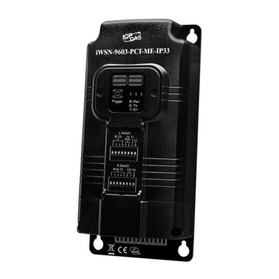
Page 2: Led Indicators
1. Appearance Descriptions LED panel cover. The LEDs statuses are shown here. Loosening two screws and opening the cover can configure the module by the DIP switches and trigger button. The screws for LED panel cover. Connector protector. Loosening two screws and open the protector can wire the CTs and voltage input cables into the module. - Page 3 3. DIP switch & trigger button Definitions Descriptions L Switch for configuring the RF channel, Tx period and AC wiring types. R Switch for configuring the Node ID, RF group ID and the PA function. Trigger button for forcing to transmit data once. Holding it 5 seconds will reset the module.
- Page 4 Items Descriptions Wiring Type F1/F2 3 Phase 4 Wire 3CT □ □ 3 Phase 3 Wire 3CT ■ □ ■:Up Single Phase 2 Wire 1CT □ ■ □:Down 3 Phase 3 wire 2CT / ■ ■ Single Phase 3 Wire 2CT □...
- Page 5 Wiring Types Wiring Methods 3 Phase 4 Wire 3CT ■:Up □:Down □ □ 3 Phase 3 Wire 3CT ■:Up □:Down ■ □ Single Phase 2 Wire 1CT ■:Up □:Down □ ■ 3 Phase 3 wire 2CT ■:Up □:Down ■ ■...
-
Page 6: Pin Assignments
R/S/T/N of 3-phase power separately. Because the pins VA and VB are also for the working power, the iWSN-9603 series module can work normally only if the voltage between VA and VB is in the range of 100VAC - 480VAC. - Page 7 D, so that the smaller measurement error can be obtained. Zone Error >5% The iWSN-9603 series modules can only be used with the specific CTs. Only the model name iWSN-9603-PCT-ME-IP33 doesn’t include CTs. Please check the accessories of the product website or...
-
Page 8: Module Installation
1. Configure the RF channel and Group ID of iWSN-200U/E to the same configuration of the iWSN-9603 series modules. 2. Set the Node ID (1 ~ 31), wiring type and Tx duty, and finish the wiring connection. -
Page 9: Product Specifications
3. Turn ON the iWSN-200U/E and iWSN-9603 series module to start the data collection. The RF_Rx LED of the iWSN-200U/E flashing once indicates the iWSN-200U/E has received one message from the iWSN-9603 series module. 1. The flash of RF_Rx LED indicates... - Page 10 Categories CAT III Data Update Rate 1, 10, 30, or 60 seconds Antenna Type Built-in Omni-directional antenna Power Consumption Input Type Three phase 100 - 480 VAC (58 - 277 VAC single phase) Includes CTs 0 (*Note) CT Type Split core CT Rogowski CT Max.
-
Page 11: Product Warranty & Customer Support
Note: Please check the accessories of the product website or contact to the ICP DAS distributor to purchase the CTs for this model if necessary. Caution 1. Danger The meter contains hazardous voltages, and should never be disassembled. Failing to follow this practice will result in serious injury or death. Any work on or near energized meters, meter sockets, or other metering equipment could induce a danger of electrical shock.
Need help?
Do you have a question about the iWSN-9603 Series and is the answer not in the manual?
Questions and answers