
Related Manuals for Belleze 014-HG-43507


Summary of Contents for Belleze 014-HG-43507
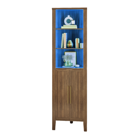
- Page 1 Brent Corner Cabinet FOLLOW US: CONTACT INFO: ITEM NO. 014-HG-43507 The instruction booklet contains IMPORTANT support@belleze.com @bellezefurniture safety information. Please read it in full and 1-800-682-6376 keep it for future reference. www.belleze.com...
- Page 2 Scan this QR Code to view our online tutorial Estimated time for assembly: 45 mins Weight limitations are as follows: Maximum Load 15 lb Maximum Load 15 lb...
- Page 3 Assemble the furniture on an empty carton, carpet, or rug to prevent scratches or damage. For safety, please keep pets and children away from the assembly area. Ensure the product is fully assembled before use. If you are missing any hardware or products, do not use it until you have restored the missing parts.
-
Page 4: Package Contents
PACKAGE CONTENTS... - Page 5 PACKAGE CONTENTS CODE DESCRIPTION Top Panel Center Panel Bottom Panel Storage Panel Left Front Leg Right Front Leg Left Side Leg Right Side Leg Left Panel Right Panel Back Leg Left Cabinet Door Right Cabinet Door v.02222023...
- Page 6 PACKAGE CONTENTS 14x + 1x 14x + 1x 23x + 2x 14x + 1x 23x + 2x 12x + 1x Install all hardware perpendicular to the opening.
- Page 7 PACKAGE CONTENTS 8x + 1x v.02222023...
- Page 8 Required tools for assembly (Not included) Assemble the back leg (11) underneath the bottom panel (3).
- Page 9 Attach magnetic catch and insert cabinet door pivot hinge bushing to the center panel (2). Insert wood dowels to the center panel (2). v.02222023...
- Page 10 Insert wood dowels to the left and right panels (9, 10). Assemble the center panel (2) to the right panel (10).
- Page 11 Assemble the left panel (9) to the center panel (2) and the right panel (10). Assemble the bottom panel (3) under the left and right panels (9, 10). v.02222023...
- Page 12 Attach cam bolts to the left and right front legs (5, 6). Insert wood dowels to the left and right side legs (7, 8).
- Page 13 Assemble the left front leg (5) to the left side leg (7). Then assemble the right front leg (6) to the right side leg (8). Note: The USB port goes through the hole in the right side leg. Assemble the right front fram to the right side of the center and bottom panel. v.02222023...
- Page 14 Secure the right side leg (8) to the bottom panel. Assemble the left front fram to the left side of the center and bottom panel.
- Page 15 Secure the left side leg (7) to the bottom panel. Assemble the top panel (1) on top of the cabinet assembly. Note: The line interface goes through the hole in the top panel. v.02222023...
- Page 16 Connect the power cord for the LED lights between the left and right legs. Use provided cable clip to hold the cord on top of the top panel.
- Page 17 Insert shelf pegs into the cabinet and put on the storage shelf panels (4). Insert pivot hinge bushings to the bottom panel. v.02222023...
- Page 18 Attach the magnetic catch plate to the cabinet doors (12, 13). Attach handles to the cabinet doors (12, 13).
- Page 19 Attach the pivot hinge plates to the cabinet doors (12, 13). v.02222023...
- Page 20 Insert the pivot hinge plate underneath the center panel and attach the right cabinet door (13) to the cabinet.
- Page 21 Insert the pivot hinge plate underneath the center panel and attach the left cabinet door (12) to the cabinet. v.02222023...
- Page 22 Attach anti-tipping straps on top of the cabinet.
- Page 23 device to prevent the furniture from tipping over. • Mark the drill position on the wall with a pencil. • Drill a small hole on the marked position. • Insert a wall anchor into the drilled hole. • Fixed the anti-tipping strap to the wall with provided screws. v.02222023...
- Page 24 Plug the power cord to a power brick and to the power outlet. YOU’RE FINISHED!
- Page 25 USER INSTRUCTION (REMOTE CONTROL) Decrease Increase Flash 7 Strobe 7 Static Color Shortcut Flash 16 Strobe 16 Press the ON button to turn on the light. Static Color Shortcut Each button is assign to a color, press the button to select your desire color. Increase Press the increase button to increase brightness in static color mode.
- Page 26 Warning Only place items on top of the product if they meet the recommended size and weight limits. Climbing on, stepping on, or placing overweighted objects on the product may cause property damage and/or injuries. Items placed onto this product must be resting on a support surface without hanging over the edges.
-
Page 27: Maintenance
© All copyright of this document belongs to BELLEZE . This document may not be printed, translated, reproduced, or distributed in whole or in part without written permission from BELLEZE. -
Page 28: Warranty
WARRANTY BELLEZE products come with a 1-year warranty from the date of delivery. Register your product on our website to enjoy our limited lifetime warranty! AFTER-SALE SERVICE Contact us at 1-800-682-6376 or email us at support@belleze.com We will send you replacement.
Need help?
Do you have a question about the 014-HG-43507 and is the answer not in the manual?
Questions and answers