Table of Contents
Advertisement
Available languages
Available languages
Technical Support and E-Warranty Certificate www.vevor.com/support
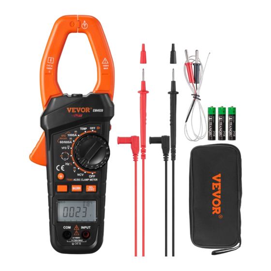
TRMS CLAMP MULTIMETER
USER MANUAL
MODEL:EM4659
We continue to be committed to provide you tools with competitive price.
"Save Half", "Half Price" or any other similar expressions used by us only represents an
estimate of savings you might benefit from buying certain tools with us compared to the major
top brands and doses not necessarily mean to cover all categories of tools offered by us. You
are kindly reminded to verify carefully when you are placing an order with us if you are
actually saving half in comparison with the top major brands.
Advertisement
Table of Contents

Related Manuals for VEVOR EM4659


Summary of Contents for VEVOR EM4659
- Page 1 Technical Support and E-Warranty Certificate www.vevor.com/support TRMS CLAMP MULTIMETER USER MANUAL MODEL:EM4659 We continue to be committed to provide you tools with competitive price. "Save Half", "Half Price" or any other similar expressions used by us only represents an estimate of savings you might benefit from buying certain tools with us compared to the major top brands and doses not necessarily mean to cover all categories of tools offered by us.
- Page 2 CustomerService@vevor.com This is the original instruction, please read all manual instructions carefully before operating. VEVOR reserves a clear interpretation of our user manual. The appearance of the product shall be subject to the product you received. Please forgive us that we won't inform you again if there are any technology or software updates on our product.
-
Page 3: Warranty
WARRANTY This instrument is warranted to be free from defects in material and workmanship for a period of one year. Any instrument found defective within one year from the delivery date and returned to the factory with transportation charges prepaid, will be repaired,adjusted, or replaced at no charge to the original purchaser. - Page 4 Warning To avoid possible electric shock or personal injury, follow these guidelines: Do not use the meter if it is damaged. Before you use the meter, inspect the case. Pay particular attention to the insulation surrounding the connectors. Inspect the test leads for damaged insulation or exposed metal. Check ...
- Page 5 indicator ( ) appears. When in Relative mode or Data Hold mode or after zeroing the display in DC current function, caution must be used because hazardous voltage may be present. Use the meter only as specified in this manual; otherwise the ...
- Page 6 Caution To avoid possible damage to the meter or to the equipment under test, follow these guidelines: Disconnect circuit power and discharge all capacitors thoroughly before testing resistance, continuity, diode,capacitor, or temperature of an object. Use the proper terminals, function and range for your measurements. ...
-
Page 7: Front Panel
FRONT PANEL Figure 1 - 7 -... - Page 8 1. Jaws Used for clamping the conductor for current measurements. The conductor should be positioned at the center of the jaws during measurement. 2. Trigger Used to open and close the jaws. 3. " " Button With the meter on, press this " "...
- Page 9 9. " " Button In dc current measurement function, press this " " button to zero the display before measurement. Press again to undo the zeroing. In other measurement functions, this button is used to enter/exit Relative mode. 10. Rotary Switch Used to select a desired function or range as well as to turn on or off the meter.
-
Page 10: Understanding The Display
This NCV sensor is located at the mark " " near the top of the clamp. It is used in non-contact ac voltage detection. 16. Jaw Wear Indicator Warning: To avoid injury, do not use the meter if the jaw wear indicator in the jaw opening is invisible. - Page 11 Symbol Meanings: ..The meter detects an input voltage > 30V. This icon is intended to remind you that hazardous voltage is present and that you must use caution to avoid electric shock..Continuity test function is selected..Inrush current measurement function is selected..
- Page 12 ..Negative sign ..AC ..The batteries are low and must be replaced immediately. 17. Bar Graph The bar graph on the top of the LCD is like the needle on an analog meter. It has an overload indicator ( ) on its right and a negative polarity indicator ( ) on its left.
- Page 13 18. Units: Unit of voltage V: Volt Unit of current A: Ampere Ω , kΩ , Unit of resistance MΩ Ω: Ohm; kΩ : Kilohm; MΩ: Megohm 1MΩ = 10 kΩ = 10 Ω Unit of capacitance nF, µF, nF: Nanofarad; µF: Microfarad; mF: Millifarad 1mF = 10 pF = 10 Unit of frequency...
-
Page 14: General Specification
GENERAL SPECIFICATION Display: 3 digits LCD Negative Polarity Indication: Negative sign "-" shown on the display automatically Sampling Rate: About 3 times/sec Jaw Opening Capability: About 50mm Max. Measurable Conductor for Current Measurements: About Ø38mm Low Battery Indication: " " shown on the display Battery: 1.5V battery, AAA or equivalent, 3 pieces Operating Environment:... - Page 15 DC Voltage Range Resolution Accuracy Overrange Indication 0.001V ± (0.8% + 5) " OL " shown 0.01V on the display 600V 0. 1V 1000V ± (1.0% + 5) Input Impedance: 10MΩ Max. Allowable Input Voltage: 1000V dc Note: 1. 1000V range is specified from 20% of range to 100% of range. 2.
- Page 16 Frequency Range: 40Hz - 400Hz ( only for 6V range ) 40Hz - 1kHz ( only for 60V, 600V and 750V ranges ) Note: Except for sine wave signal and triangular wave signal measurements, accuracy specifications for ac voltage measurements do not apply to measurements of signals whose frequencies are >...
- Page 17 AC Current Range Resolution Accuracy 0.01A ± (2.5% + 6) VFD current: ± (5.0% + 15) 600A 0.1A Inrush current: not specified 1000A Frequency Range: 50Hz ~ 60Hz Reading: True rms Overrange Indication: " OL " shown on the display Integration Time: 100ms ( only for inrush current measurements ) Note: 1.
- Page 18 Frequency Range Resolution Accuracy Remark 9.999Hz 0.001Hz 99.99Hz 0.01Hz 999.9Hz 0.1Hz ± ( 1.0% + 5) Autorange 9 999kHz 0 001kHz 99.99kHz 0.01kHz 999.9kHz 0. 1kHz 9.999MHz 0.001MHz not specified For frequency measurements with the rotary switch in the"H%" position, the amplitude of the input signal is required tobe in the range of 2V rms to 20V rms.
- Page 19 Capacitance Range Resolution Accuracy Remark 6.000nF 0.001nF 60.00nF 0.01nF 600.0nF 0. 1nF 6.000uF 0.001uF ± (5.0% + 5) Autorange 60.00uF 0.01uF 600.0uF 0.1uF 6.000mF 0.001mF ± (5.0% + 20) 60.00mF 0.01mF not specified Note: 1. If the capacitance being measured is > 60mF, the display may show a reading, but the measurement result may be wrong or inaccurate.
- Page 20 Temperature Sensor: K Type thermocouple Note: 1. Accuracy does not include error of the thermocouple probe. 2. Accuracy specification assumes ambient temperature is stable to ± 1°C. For ambient temperature changes of ± 5°C, rated accuracy applies after 1 hour. 3.
- Page 21 OPERATING INSTRUCTION Data Hold Mode Briefly press the " " button to enter the Data Hold mode. The present reading is held on the display, and the symbol " " appears on display as an indicator. To exit the Data Hold mode, briefly press this button again. The symbol " "...
- Page 22 between the reference and the new measurement. 5. To exit the Relative mode, briefly press this " " button again. The symbol " " disappears. Note: 1. When you use Relative mode, the actual value of the object under test must not exceed the full-scale value of the present range.
- Page 23 ( " " appears ) and the maximum reading ( " " appears ). 3. To pause MIN MAX recording, briefly press the " " button. The symbol " " is displayed. To resume MIN MAX recording, briefly press the " "...
- Page 24 4. Connect the test leads across the source or circuit to be tested. 5. Read the voltage reading on the primary display. For DC voltage measurements, the polarity of the red test lead connection will be indicated as well, and the secondary display will show the ambient temperature. For AC voltage measurements, the secondary display will show the frequency of the ac voltage being measured.
- Page 25 Measuring DC Current 1. Make sure that all the test leads have been removed from the meter. Then set the rotary switch to desired current range position ( " " or " " position ). 2. Press the Function Selector Button until the symbol " "...
- Page 26 a voltage > 1000V. Measuring AC Current 1. Make sure that all the test leads have been removed from the meter. Then set the rotary switch to desired current range position ( " " or " " position ). 2. Press the Function Selector Button until the symbol " "...
- Page 27 Measuring VFD Current 1. Make sure that all the test leads have been removed from the meter. Then set the rotary switch to desired current range position ( " " or " " position ). 2. Press the Function Selector Button until both the symbols " "...
- Page 28 Measuring Inrush Current Inrush current is surge current that occurs when an electrical device is first powered on. Once the device has reached its normal working condition, the current stabilizes. To capture the inrush current reading: 1. Make sure that the system to be tested has been turned off. 2.
- Page 29 measurement unit and the symbol" " is absent from the display. 4. Connect the test leads across the resistor to be tested. 5. Wait until the reading on the primary display is stable, then read the resistance reading on the primary display. The secondary display shows the ambient temperature.
- Page 30 and the red test leads to the " INPUT " terminal. 2. Set the rotary switch to the position. 3. Press the Function Selector Button until the symbol " " appears on the screen. 4. Connect the test leads across the circuit to be tested. 5.
- Page 31 capacitance reading on the primary display. The secondary display shows the ambient temperature. Note: 1. Before measurement, make sure that the capacitor to be tested has been discharged thoroughly. 2. For measurements > 10uF, it may take about 30 secs for the meter to complete measurement and stabilize reading.
- Page 32 Measuring Temperature Note To avoid possible damage to the meter or other equipment, remember that while the meter is rated for -20oC to +1000oC and -4oF to 1832oF, the K Type Thermocouple provided with the meter is rated to 250oC. For temperature out of that range, use a higher rated thermocouple.
- Page 33 2. Move the NCV sensor at the " " mark on the meter clamp close to the object to be tested. When the meter detects electric field generated by ac voltage, the red LED on the meter will flash and the meter will indicate the intensity of the electric field being detected.
-
Page 34: Maintenance
5. Because of the meter's detection limit, a line ( or conductor) under test may be electrically live even if the buzzer does not sound, the red LED does not flash and the display does not indicate the presence of electric field. - Page 35 Periodically wipe the case with a damp cloth and a little mild detergent. Do not use abrasives or solvents. Dirt or moisture in the terminals can affect readings. Clean the terminals as follows: 1. Set the rotary switch to OFF position and remove all the test leads from the meter.
- Page 36 Replacing the Batteries Warning To avoid false readings,which could lead to possible electric shock or personal injury,replace the batteries as soon as the low battery indicator ) appears. Turn off the meter,remove the test leads from the meter and the meter clamp from any conductor under test before opening the case or the battery cover.
- Page 37 NOTE 1. This manual is subject to change without notice. 2. Our company will not take the other responsibilities for any loss. 3. The contents of this manual can not be used as the reason to use the meter for any special application. DISPOSAL OF THIS ARTICLE Dear Customer, If you at some point intend to dispose of this article, then please...
- Page 38 EUREP UK LTD UNIT 2264, 100 OCK STREET, ABINGDON OXFORDSHIRE ENGLAND OX14 5DH EUREP GmbH Unterlettenweg 1a, 85051 Ingolstadt, Germany Importer: WAITCHX Address: 250 bis boulevard Saint-Germain 75007 Paris Importer: FREE MOOD LTD Address: 2 Holywell Lane, London, England, EC2A 3ET Manufacturer: Zhangzhou Eastern Intelligent Meter Co.,Ltd.
- Page 40 Technical Support and E-Warranty Certificate https://www.vevor.com/support...
- Page 41 Technische Unterstützung und E-Garantie-Zertifikat www.vevor.com/support TRMS ZANGENMULTIMETER ZANGENMULTIMETER MODEL:EM4659 Wir sind kontinuierlich bestrebt, Ihnen Werkzeuge zu wettbewerbsfähigen Preisen zu liefern. „Um die Hälfte sparen“, „Halber Preis“ oder andere ähnliche Ausdrücke, die von uns verwendet werden, stellen nur einen Schätzwert für die Ersparnis dar, die Sie beim Kauf bestimmter Werkzeuge bei uns im Vergleich zu den großen Top-Marken erzielen können,...
- Page 43 CustomerService@vevor.com Dies ist die Original-Bedienungsanleitung, bitte lesen Sie alle Anweisungen vor der Inbetriebnahme sorgfältig durch. VEVOR behält sich eine klare Auslegung unserer Bedienungsanleitung vor. Das Aussehen des Produkts entspricht dem Produkt, das Sie erhalten haben. Wir bitten um Ihr Verständnis, dass wir Sie nicht mehr informieren werden, wenn es irgendwelche Technologie- oder Software-Updates für unser Produkt gibt.
-
Page 44: Garantie
GARANTIE Dieses Gerät hat eine Garantie von einem Jahr für Material- und Verarbeitungsdefekte. Jedes Gerät, das sich innerhalb eines Jahres ab Lieferdatum als defekt erweist und mit vorausbezahlten Transportkosten an das Werk zurückgeschickt wird, wird kostenlos repariert, eingestellt oder ersetzt. Diese Garantie gilt nicht für Zubehörteile wie Batterien. Wenn der Defekt durch Missbrauch oder anormale Betriebsbedingungen verursacht wurde, wird die Reparatur zu einem geringen Betrag in Rechnung gestellt. - Page 45 Warnung Um einen Stromschlag oder Verletzungen zu vermeiden, beachten Sie bitte die folgenden Hinweise: Verwenden Sie das Messgerät nicht, wenn es beschädigt ist. Überprüfen Sie das Gehäuse, bevor Sie das Messgerät verwenden. Achten Sie besonders auf die Isolierung um die Anschlüsse. Prüfen Sie die Messleitungen auf beschädigte Isolierung oder ...
- Page 46 Nehmen Sie die Messleitungen vom Messgerät und die Klemme von jedem zu prüfenden Leiter ab, bevor Sie den Batteriedeckel oder das Gehäuse öffnen. Betreiben Sie das Messgerät nicht, wenn die Batterieabdeckung oder Teile des Gehäuses entfernt oder gelockert wurden. Um falsche Messwerte zu vermeiden, die zu einem Stromschlag oder ...
- Page 47 Sammelschienen, Verteilerkästen, Schaltern und Steckdosen in der festen Installation, und Geräte für den industriellen Einsatz sowie einige andere Geräte, z. B. stationäre Motoren mit festem Anschluss an eine feste Installation.Verwenden Sie das Messgerät nicht für Messungen in der Messkategorie IV. Achtung Um mögliche Beschädigungen des Messgeräts oder der zu prüfenden Ausrüstung zu vermeiden, befolgen Sie bitte die folgenden...
- Page 48 und die Entfernung von diesen ist zulässig. VORDERSEITE Figure 1 - 8 -...
- Page 49 1. Klemmbacken Dient zum Festklemmen des Leiters bei Strommessungen. Der Leiter sollte sich während der Messung in der Mitte der Klemmbacken befinden. 2. Auslöser Dient zum Öffnen und Schließen der Klemmbacken. 3. „ Taste “ Bei eingeschaltetem Messgerät drücken Sie die Taste" ", um die Hintergrundbeleuchtung ein- oder auszuschalten.
- Page 50 9. „ Taste “ In der Funktion Gleichstrommessung drücken Sie diese Taste „ “, um die Anzeige vor der Messung auf null zu stellen. Drücken Sie erneut, um den Nullabgleich rückgängig zu machen. Bei anderen Messfunktionen wird diese Taste verwendet, um den Relativmodus aufzurufen oder zu verlassen.
- Page 51 14. LED-Beleuchtung 15. NCV Sensor Dieser NCV-Sensor befindet sich an der Markierung „ nahe der “ Oberseite der Klemme. Er wird zur berührungslosen Erkennung von Wechselspannungen verwendet. 16. Anzeige für Backenverschleiß Warnung: Um Verletzungen zu vermeiden, verwenden Sie das Messgerät nicht, wenn die Anzeige für den Backenverschleiß...
- Page 52 Bedeutung der Symbole: ..Das Messgerät erkennt eine Eingangsspannung > 30V. Dieses Symbol weist Sie darauf hin, dass gefährliche Spannungen vorhanden sind und dass Sie vorsichtig sein müssen, um einen Stromschlag zu vermeiden..Die Funktion Durchgangsprüfung ist ausgewählt..Die Funktion Einschaltstrommessung ist ausgewählt..
- Page 53 ..DC (GLEICHSTROM) ..Negatives Zeichen ..AC (WECHSELSTROM) ..Die Batterien sind schwach und müssen sofort ersetzt werden. 17. Balkendiagramm Das Balkendiagramm am oberen Rand des LCD-Bildschirms ist wie die Nadel eines analogen Messgeräts. Auf der rechten Seite befindet sich eine Überlastanzeige ( ) und auf der linken Seite eine Anzeige für negative Polarität ( ).
- Page 54 18. Einheiten: Einheit der Spannung V: Volt Einheit der Stromstärke A: Ampere Ω , kΩ , Einheit des Widerstands MΩ Ω: Ohm; kΩ : Kilohm; MΩ: Megohm 1MΩ = 10 kΩ = 10 Ω Einheit der Kapazität nF, µF, nF: Nanofarad; µF: Mikrofarad; mF: Millifarad 1mF = 10 pF = 10 Einheit der Frequenz...
-
Page 55: Allgemeine Spezifikationen
ALLGEMEINE SPEZIFIKATIONEN Display: 3 stellige LCD-Anzeige Anzeige der negativen Polarität: Negatives Vorzeichen „-“ wird automatisch auf dem Display angezeigt. Abtastrate: Etwa 3 Mal/Sek. Kapazität der Backenöffnung: Etwa 50mm Max. Messbarer Leiter für Strommessungen: Etwa Ø38mm Anzeige für schwache Batterie: „ wird auf dem Display “... -
Page 56: Spezifikationen
SPEZIFIKATIONEN Die Genauigkeit ist für einen Zeitraum von einem Jahr nach Kalibrierung angegeben, bei 18 C bis 28 C und einer relativen Luftfeuchtigkeit < 75%. Sofern nicht anders angegeben, liegt die Genauigkeit zwischen 5 % und 100 % des Bereichs. Die Angaben zur Genauigkeit erfolgen in Form von: ±([% des Messwerts] +[Anzahl der niedrigst wertigen Stellen]) Gleichstromspannung... - Page 57 Wechselstromspannung Anzeige der Reichweite Auflösung Genauigkeit Messbereichsübers chreitung 0.001V ± (0.8% + 5) „OL“ wird auf dem 0.01V Display angezeigt. 600V 0. 1V ± (1.2% + 5) 750V ± (2.5% + 15) VFD 750V Eingangswiderstand: 10MΩ Frequenzbereich: 40Hz - 400Hz (nur für den 6-V-Bereich) 40Hz - 1kHz (nur für 60-V-, 600-V- und 750-V-Bereiche) Hinweise: Abgesehen von der Messung von Sinus- und...
- Page 58 Gleichstrom Reichweite Auflösung Genauigkeit Anzeige der Messbereichsübersc hreitung 0.01A ± (3% + 10) „OL“ wird auf dem 600A 0. 1A Display angezeigt. ± (3% + 6) 1000A Hinweise: 1. Die Bereiche 60A und 600A liegen zwischen 10 % und 100% des Bereiches.
- Page 59 Hinweise: 1. Die Bereiche 60A und 600A reichen von 10 % bis 100 % des Bereichs. Der 1000A-Bereich reicht von 20 % bis 100 % des Bereichs. 2. Im 1000A-Bereich, wenn der gemessene Strom 1000A beträgt, ertönt der eingebaute Summer, und wenn der Strom > 1010A ist, wird auf dem Display „OL“...
- Page 60 bis 20 V ("Effektivwert") liegen. Wenn das Messgerät Wechselspannung und Frequenz gleichzeitig misst und sich der Drehschalter in der Position " " befindet, beträgt der Frequenzmessbereich 10Hz bis 1kHz, und die Eingangsspannung für Frequenzmessungen muss > 2V sein (je höher die Frequenz des Eingangssignals, desto höher die erforderliche Eingangsspannung).
- Page 61 Kapazität Reichweite Auflösung Genauigkeit Bemerkung 6.000nF 0.001nF 60.00nF 0.01nF 600.0nF 0. 1nF 6.000uF 0.001uF ± (5.0% + 5) Autorange 60.00uF 0.01uF 600.0uF 0.1uF 6.000mF 0.001mF ± (5.0% + 20) 60.00mF 0.01mF nicht angegeben Hinweise: 1. Wenn die gemessene Kapazität > 60 mF ist, zeigt das Display zwar einen Messwert an, aber das Messergebnis kann falsch oder ungenau sein.
- Page 62 Temperatur Reichweite Auflösung Genauigkeit Anzeige der Messbereichsü berschreitung - 20°C ~ 0°C ± (6.0% + 5°C) 0°C ~ 400°C ± ( 1.5% + 4°C) 1°C 400°C ~ 1000°C ± ( 1.8% + 5°C) - 4°F ~ 32°F ± (6.0% + 9°F) 32°F ~ 752°F ±...
- Page 63 Durchgangsprüfung Reichweite Beschreibung Der eingebaute Summer ertönt, wenn der Widerstand weniger als 50Ω beträgt. Der Summer ertönt nicht, wenn der Widerstand mehr als 100Ω beträgt. Der Summer ertönt möglicherweise, wenn der Widerstand zwischen 50Ω und 100Ω liegt. Diodentest Reichweit Beschreibung Bemerkung Der ungefähre Spannungsabfall in Leerlaufspannung: etwa 4...
- Page 64 Hinweise: Bei der berührungslosen Wechselspannungserkennung ist die Taste „ deaktiviert. “ Verwendung des Relativ-Modus Der Relativ-Modus ist in einigen Funktionen verfügbar. Wählen Sie Relativ-Modus, so speichert das Messgerät den aktuellen Messwert als Referenz für nachfolgende Messungen. 1. Stellen Sie das Messgerät auf die gewünschte Funktion oder den gewünschten Bereich ein.
- Page 65 3. Wenn das Display "OL" anzeigt, bedeutet dies, dass die Reichweite überschritten wurde. 4. Mit der Ausnahme der Kapazitätsfunktion geht das Messgerät in den manuellen Messbereich über, wenn Sie den Relativ-Modus aufrufen. 5. Für Frequenz-, Einschaltdauer-, Dioden-, Durchgangs- und Einschaltstrommessfunktionen sowie berührungslose Wechselspannungserfassungsfunktionen ist der Relativmodus nicht verfügbar.
- Page 66 Taste „ “. Das Symbol „ “ wird ausgeblendet. 4. Um den MIN/MAX-Modus zu verlassen und alle gespeicherten Messwerte zu löschen, halten Sie die Taste „ “ etwa 2 Sekunden lang gedrückt; das Messgerät kehrt dann zum Normalbetrieb zurück. Hinweise: 1.
- Page 67 5. Lesen Sie den Spannungswert auf dm primärem Display ab. Bei Gleichspannungsmessungen wird auch die Polarität des roten Messleitungsanschlusses angezeigt, und das sekundäre Display zeigt die Umgebungstemperatur an. Bei Wechselspannungsmessungen zeigt das sekundäre Display die Frequenz der gemessenen Wechselspannung an. Hinweise: Um einen Stromschlag oder eine Beschädigung des Messgeräts zu vermeiden, darf zwischen den Buchsen keine höhere Spannung als 1000...
- Page 68 Messung von Gleichstrom 1. Stellen Sie sicher, dass alle Messleitungen vom Messgerät entfernt wurden. Stellen Sie dann den Drehschalter auf die gewünschte Strombereichsposition (Position „ oder „ “ “ 2. Drücken Sie die Funktionswahltaste, bis das Symbol „ auf dem “...
- Page 69 Tipp: Die Stromrichtung ist das Gegenteil der Elektronenflussrichtung. 3. Verwenden Sie das Messgerät nicht zur Messung des Stroms eines Stromkreises, wenn der Stromkreis eine Spannung von mehr als 1000 V enthält. Messung von Wechselstrom 1. Stellen Sie sicher, dass alle Messleitungen vom Messgerät entfernt wurden.
- Page 70 Minuten, damit sich das Messgerät aufwärmen kann, bevor Sie mit der Strommessung beginnen. Dies ist für genaue Messungen erforderlich. 2. Verwenden Sie das Messgerät nicht zur Messung des Stroms eines Stromkreises, wenn der Stromkreis eine Spannung von mehr als 1000 V enthält.
- Page 71 werden, werden eliminiert. Um mögliche Stromschläge oder Verletzungen zu vermeiden, verwenden Sie niemals die Strommessfunktion des VFD, um die Anwesenheit von gefährlichen Strömen zu überprüfen. Es können Ströme vorhanden sein, die größer sind als die angegebenen. 2. W arten Sie nach dem Einschalten des Messgeräts etwa 5 bis 10 Minuten, damit sich das Messgerät aufwärmen kann, bevor Sie mit der Strommessung beginnen.
- Page 72 Die zu prüfende Leitung sollte in der Mitte der Klemmbacken positioniert werden. 5. Schalten Sie das zu prüfende System ein. Der Wert des Einschaltstroms wird auf dem Display angezeigt und gehalten. Messung des Widerstands 1. Schließen Sie die schwarze Messleitung an die „COM“ Buchse und die rote Messleitung an die „INPUT“...
- Page 73 1. Schließen Sie die schwarze Messleitung an die „COM“ Buchse und die rote Messleitung an die „INPUT“ Buchse an. Hinweise: Die Polarität der roten Messleitung ist positiv. 2. Stellen Sie den Drehschalter auf die Position 3. Drücken Sie die Funktionswahltaste, bis das Symbol „ auf dem “...
- Page 74 Messung der Kapazität 1. Schließen Sie die schwarze Messleitung an die „COM“ Buchse und die rote Messleitung an die „INPUT“ Buchse an. 2. Stellen Sie den Drehschalter auf die Position 3. Drücken Sie die Funktionswahltaste, bis das Display eine Kapazitätsmesseinheit ( nF) anzeigt. 4.
- Page 75 die rote Messleitung an die „INPUT“ Buchse an. 2. Stellen Sie den Drehschalter auf die Position „ “ 3. Schließen Sie die Messleitungen an die zu prüfende Quelle oder den Stromkreis an. 4. Das primäre Display zeigt die Frequenz an, das sekundäre Display die Einschaltdauer des gemessenen Rechtecksignals.
- Page 76 1. Stellen Sie den Drehschalter auf die Position TEMP. Das sekundäre Display zeigt die Umgebungstemperatur an. 2. Schließen Sie den negativen „-“ Stecker des Thermoelementes Typ K an die „COM“ Buchse und den positiven „+“ Stecker des Thermoelementes Typ K an die „INPUT“ Buchse an. 3.
- Page 77 Hinweise: 1. Erkennungsbereich: 90V - 1000V Erforderliche Spannungsfrequenz: 50Hz/60Hz 3. Die optimale Erfassungsposition des Messgeräts befindet sich an der Markierung „ auf der Messzange. “ 3. Wenn eine Wechselspannung nicht innerhalb der Erkennungskapazität/Distanz des Messgeräts liegt, kann das Messgerät diese Spannung nicht erkennen. 4.
- Page 78 Verwenden Sie das Messgerät nicht, wenn es abnormal funktioniert oder Fehlfunktionen aufweist. 7. Um einen Stromschlag zu vermeiden, berühren Sie keinen der Leiter mit der Hand oder der Haut. 8. Um Störungen zu vermeiden, sollten Sie die berührungslose Wechselspannungserfassung nicht in einer Umgebung mit starken elektromagnetischen Feldern durchführen;...
- Page 79 wenig mildem Reinigungsmittel ab. Verwenden Sie keine Schleif- oder Lösungsmittel. Schmutz oder Feuchtigkeit in den Klemmen können die Messwerte beeinträchtigen. Reinigen Sie die Klemmen wie folgt: 1. Stellen Sie den Drehschalter auf die Position OFF und entfernen Sie alle Messleitungen vom Messgerät. 2.
- Page 80 Austauschen der Batterien Warnung Um falsche Messwerte zu vermeiden, die zu einem Stromschlag oder Verletzungen führen können, tauschen Sie die Batterien aus, sobald die Anzeige für schwache Batterien ( ) erscheint. Schalten Sie das Messgerät aus, entfernen Sie die Messleitungen vom Messgerät und die Messzange von jedem zu prüfenden Leiter, bevor Sie das Gehäuse oder den Batteriedeckel öffnen.
- Page 81 HINWEISE 1. Dieses Handbuch kann ohne vorherige Ankündigung geändert werden. 2. Unser Unternehmen übernimmt keine weitere Verantwortung für etwaige Verluste. 3. Der Inhalt dieses Handbuchs kann nicht als Grund für die Verwendung des Messgeräts für eine spezielle Anwendung herangezogen werden. ENTSORGUNG DES ARTIKELS Liebe Kunden, Wenn Sie diesen Artikel irgendwann entsorgen wollen, dann bedenken Sie...
- Page 82 EUREP UK LTD UNIT 2264, 100 OCK STREET, ABINGDON OXFORDSHIRE ENGLAND OX14 5DH EUREP GmbH Unterlettenweg 1a, 85051 Ingolstadt, Germany Importeur: WAITCHX Adresse: 250 bis boulevard Saint-Germain 75007 Paris Importeur: FREE MOOD LTD Adresse: 2 Holywell Lane, London, England, EC2A 3ET Hersteller: Zhangzhou Eastern Intelligent Meter Co.,Ltd.
- Page 84 Technische Unterstützung und E-Garantie-Zertifikat https://www.vevor.com/support...
- Page 85 PINCE MULTIMÈTRE TRMS MANUEL D'UTILISATION MODÈLE : EM4659 Nous nous engageons toujours à vous fournir des outils à des prix compétitifs. "Réduction de 50%", "Moitié Prix" ou toute autre expression similaire utilisée représente uniquement une estimation des économies que vous pourriez bénéficier en achetant certains outils chez nous par rapport aux grandes marques et ne couvre pas forcément toutes les...
- Page 86 CustomerService@vevor.com Ceci est l'instruction originale, veuillez lire attentivement toutes les instructions du manuel avant de l'utiliser. VEVOR se réserve une interprétation claire de notre manuel d'utilisation. L'apparence du produit est soumise au produit que vous avez reçu. Veuillez nous pardonner de ne pas vous informer à nouveau s'il y a des mises à jour technologiques ou logicielles sur notre produit.
-
Page 87: Informations De Sécurité
GARANTIE Cet instrument est garanti contre tout défaut de matériau et de fabrication pour une période d'un an. Tout instrument jugé défectueux dans un délai d'un an à compter de la date de livraison et renvoyé à l'usine, frais de transport payés d'avance, sera réparé, ajusté... - Page 88 Avertissement Pour éviter tout risque de choc électrique ou de blessure corporelle, suivez ces directives : N'utilisez pas le compteur s'il est endommagé. Avant d'utiliser le compteur, inspectez le boîtier. Faites particulièrement attention à l'isolation entourant les connecteurs. Inspectez les fils de test pour vérifier que l'isolation n'est pas ...
- Page 89 Retirez les cordons de test de l'appareil et la pince de tout conducteur testé avant d'ouvrir le couvercle de la batterie ou le boîtier. N'utilisez pas l'appareil si le couvercle de la batterie ou des parties du boîtier ont été retirés ou desserrés. Pour éviter les fausses lectures, qui pourraient entraîner une décharge ...
- Page 90 usage industriel et certains autres équipements, par exemple, les moteurs stationnaires avec une connexion permanente à l'installation fixe. N'utilisez pas le compteur pour des mesures relevant de la catégorie de Mesure IV. Attention Pour éviter d'endommager l'appareil ou l'équipement testé, suivez les instructions suivantes : Débranchez l'alimentation du circuit et déchargez complètement tous ...
-
Page 91: Face Avant
FACE AVANT Figure 1 - 7 -... - Page 92 1. Mâchoires Utilisé pour serrer le conducteur pour les mesures de courant. Le conducteur doit être positionné au centre des mâchoires pendant la mesure. 2. Déclencheur Utilisé pour ouvrir et fermer les mâchoires. 3. Bouton " " Lorsque le compteur est allumé, appuyez sur ce bouton " "...
- Page 93 9. Bouton " " Dans la fonction de mesure du courant continu, appuyez sur ce bouton " " pour mettre à zéro l'affichage avant la mesure. Appuyez à nouveau sur ce bouton pour annuler la mise à zéro. Dans les autres fonctions de mesure, ce bouton est utilisé pour entrer/sortir du mode Relatif.
-
Page 94: Comprendre L'affichage
15. Capteur NCV Ce capteur NCV est situé au niveau de la marque " " près du sommet de la pince. Il est utilisé pour la détection de la tension alternative sans contact. 16. Indicateur d'Usure des Mâchoires Avertissement : Pour éviter toute blessure, n'utilisez pas le lecteur si le témoin d'usure de la mâchoire situé... - Page 95 Signification des Symboles : ..Le compteur détecte une tension d'entrée > 30V. Cette icône est destinée à vous rappeler qu'une tension dangereuse est présente et que vous devez faire preuve de prudence pour éviter toute décharge électrique..La fonction de test de continuité est sélectionnée..
- Page 96 ..CC ..Signe négatif ..CA ..Les piles sont faibles et doivent être remplacées immédiatement. 17. Bargraphe Le graphique à barres en haut de l'écran LCD est comme l'aiguille d'un compteur analogique. Il comporte un indicateur de surcharge ( ) sur sa droite et un indicateur de polarité...
- Page 97 18. Unités : Unité de tension V : Volt Unité de courant A : Ampère Ω , kΩ , Unité de résistance MΩ Ω: Ohm; kΩ : Kilohm; MΩ: Mégohm 1MΩ = 10 kΩ = 10 Ω Unité de capacitance nF, µF, nF: Nanofarad;...
-
Page 98: Spécification
SPÉCIFICATION GÉNÉRALE Affichage : LCD 3 chiffres Indication de la Polarité Négative : Le signe négatif "-" est affiché sur l'écran automatiquement Taux d'Échantillonnage : Environ 3 fois/seconde Capacité d'Ouverture des Mâchoires : Environ 50 mm Conducteur Mesurable du Courant Max. Mesures : Environ Ø... - Page 99 Les spécifications de précision prennent la forme de : ±([% de la lecture] + [nombre de chiffres les moins significatifs]) Tension CC Gamme Résolution Précision Indication de Dépassement de Gamme 0.001V ± (0.8% + 5) " OL " s'affiche sur 0.01V l'écran 600V...
- Page 100 Tension CA Gamme Résolution Précision Indication de Dépassement de Gamme 0.001V ± (0.8% + 5) " OL " s'affiche sur 0.01V l'écran 600V 0. 1V ± (1.2% + 5) 750V ± (2.5% + 15) VFD 750V Impédance d'Entrée : 10MΩ Gamme de Fréquences : 40Hz - 400Hz (uniquement pour la gamme 6V) 40Hz - 1kHz (seulement pour les gammes 60V, 600V et 750V)
- Page 101 Courant CC Gamme Résolution Précision Indication de Dépassement de Gamme 0.01A ± (3% + 10) " OL " s'affiche sur 600A 0. 1A l'écran ± (3% + 6) 1000A Remarque : 1. Les gammes 60A et 600A sont spécifiées de 10% de la gamme à 100% de la gamme.
- Page 102 tégré retentit, et si le courant est > 1010A, l'écran affiche " OL ". Résistance Gamme Résolution Précision Indication de Dépassement de Gamme 600.0 Ω 0.1Ω ± (1.0% + 5) 6.000 kΩ 0.001kΩ 60.00 kΩ 0.01kΩ " OL " s'affiche sur 600.0 kΩ...
- Page 103 doit être > 1/3 de la plage de tension actuelle (plus la fréquence du signal d'entrée est élevée, plus la tension d'entrée requise est élevée). Lorsque le compteur mesure le courant VFD et la fréquence du courant en même temps, la gamme de mesure de la fréquence est de 10 Hz à 1 kHz, et l'amplitude du courant pour la mesure de la fréquence doit être >...
- Page 104 l'appareil et des fils. Température Gamme Résolution Précision Indication de Dépassement de Gamme - 20°C ~ 0°C ± (6.0% + 5°C) 0°C ~ 400°C ± (1.5% + 4°C) 1°C 400°C ~ 1000°C ± (1.8% + 5°C) - 4°F ~ 32°F ±...
-
Page 105: Instruction De Fonctionnement
Test de Continuité Gamme Description Le buzzer intégré se déclenchera si la résistance est inférieure à environ 50Ω. Le buzzer ne sonnera pas si la résistance est supérieure à 100Ω. Le buzzer peut ou non retentir si la résistance est comprise entre 50Ω... - Page 106 Remarque : Dans la fonction de détection de la tension alternative sans contact, le bouton " " est désactivé. Utilisation du Mode Relatif Le mode relatif est disponible dans certaines fonctions. Sélectionnez Le mode relatif permet au lecteur de stocker la lecture actuelle comme référence pour les mesures suivantes.
- Page 107 5. Pour les fonctions de mesure de fréquence, de rapport cyclique, de diode, de continuité et de courant d'appel et les fonctions de détection de tension alternative sans contact, le mode relatif n'est pas disponible. 6. Dans la fonction de mesure du courant continu, le bouton " "...
- Page 108 1. En mode gamme automatique, le multimètre passe en gamme manuelle dans la gamme actuelle lorsque vous entrez dans le mode MIN MAX. 2. Lorsque l'écran affiche " OL ", cela signifie qu'il y a dépassement de la plage. 3. Le mode MIN MAX n'est pas disponible pour les fonctions de mesure de la fréquence, du rapport cyclique, de la capacité, de la diode, de la continuité...
- Page 109 Mesure de la Tension du VFD 1. Connectez le fil de test noir à la borne " COM ", et le fil de test rouge à la borne " INPUT ". 2. Placez le commutateur rotatif sur la position " ".
- Page 110 une fois sur le bouton " " pour remettre à zéro l'affichage principal. 4. Appuyez sur le déclencheur et serrez les mâchoires autour d'un conducteur à tester. Assurez-vous que les mâchoires sont parfaitement fermées. Note : Il ne faut serrer qu'un seul conducteur. La mesure de deux ou ...
- Page 111 Placez ensuite le commutateur rotatif sur la position de la gamme de courant souhaitée ( position " " ou " " ). 2. Appuyez sur le Bouton de Sélection des Fonctions jusqu'à ce que le symbole " " s'affiche et que le symbole " "...
- Page 112 courant souhaitée (position " " ou " " ). 2. Appuyez sur le bouton de sélection des fonctions jusqu'à ce que les symboles " " et " " s'affichent. 3. Appuyez sur le déclencheur et serrez les mâchoires autour d'un conducteur à...
- Page 113 appareil électrique est mis sous tension pour la première fois. Une fois que l'appareil a atteint son état de fonctionnement normal, le courant se stabilise. Pour capturer la lecture du courant d'appel : 1. Assurez-vous que le système à tester a été mis hors tension. 2.
- Page 114 " s’affiche. 4. Connectez les fils d'essai sur la résistance à tester. 5. Attendez que la lecture sur l'affichage primaire soit stable, puis lisez la lecture de la résistance sur l'affichage primaire. L'affichage secondaire indique la température ambiante. Note : 1.
- Page 115 1. Connectez le fil de test noir à la borne " COM ", et le fil d'essai rouge à la borne " INPUT ". 2. Mettez le commutateur rotatif en position 3. Appuyez sur le bouton de sélection des fonctions jusqu'à ce que le symbole "...
- Page 116 6. Attendez que la lecture sur l'affichage primaire soit stable, puis lisez la lecture de la capacitance sur l'affichage primaire. L'affichage secondaire indique la température ambiante. Note : 1. Avant la mesure, assurez-vous que le condensateur à tester a été déchargé...
- Page 117 Remarque Pour éviter d'endommager l'appareil ou d'autres équipements, n'oubliez pas que, bien que l'appareil soit conçu pour une utilisation de -20°C à +1000°C et de -4°F à 1832°F, le thermocouple de type K fourni avec l'appareil est conçu pour une utilisation à 250°C.
- Page 118 2. Déplacez le capteur NCV au niveau du repère" " sur la mâchoire du compteur à proximité de l'objet à tester. Lorsque le compteur détecte un champ électrique généré par une tension alternative, la LED rouge du compteur clignote et le compteur indique l'intensité du champ électrique détecté.
-
Page 119: Entretien
etc. 5. En raison de la limite de détection du compteur, une ligne (ou un conducteur) testée peut être sous tension même si le buzzer ne retentit pas, la LED rouge ne clignote pas et l'écran n'indique pas la présence d'un champ électrique. 6. - Page 120 Rangez le lecteur dans un endroit sec lorsqu'il n'est pas utilisé. Ne le stockez pas dans un environnement où règne un champ électromagnétique intense. Entretien Général Essuyez périodiquement le boîtier avec un chiffon humide avec un peu de détergent doux. N'utilisez pas d'abrasifs ou de solvants. La présence de saleté...
- Page 121 Remplacement des Piles Avertissement Pour éviter les fausses lectures, qui pourraient entraîner un choc électrique ou des blessures corporelles, remplacez les piles dès que l'indicateur de piles faibles ( ) s’affiche. Éteignez l'appareil, retirez les fils de test de l'appareil et la pince de l'appareil de tout conducteur testé...
- Page 122 NOTE 1. Ce manuel est susceptible d'être modifié sans préavis. 2. Notre société ne prendra pas les autres responsabilités pour toute perte. 3. Le contenu de ce manuel ne peut pas être utilisé comme une raison d'utiliser le compteur pour une application spéciale. MISE AU REBUT DE CET ARTICLE Cher client, Si vous comptez un jour vous débarrasser de cet article,...
- Page 123 EUREP UK LTD UNITÉ 2264, 100 RUE OCK, ABINGDON OXFORDSHIRE ANGLETERRE OX14 5DH EUREP GmbH Unterlettenweg 1a, 85051 Ingolstadt, Allemagne Importateur : WAITCHX Adressse : 250 bis boulevard Saint-Germain 75007 Paris Importateur : FREE MOOD LTD Adresse : 2 Holywell Lane, Londres, Angleterre, EC2A 3ET Fabricant : Zhangzhou Eastern Intelligent Meter Co.,Ltd.
- Page 124 Assistance Technique et Certificat de Garantie Électronique https://www.vevor.com/support...
Need help?
Do you have a question about the EM4659 and is the answer not in the manual?
Questions and answers
how to set unit em4659 to detect parasitic draw
To detect parasitic draw using the VEVOR EM4659 clamp multimeter, follow these steps:
1. Prepare the Vehicle: Ensure the vehicle is turned off, and all accessories are off. Wait for the vehicle's electronics to enter sleep mode (this may take several minutes to an hour).
2. Set the Multimeter:
- Remove all test leads from the meter.
- Turn the rotary switch to the DC current (A) mode.
- Use the function button to select DC measurement.
3. Clamp the Meter:
- Open the clamp and place it around the battery negative cable.
- Ensure only one conductor is inside the clamp, and it is centered for accurate readings.
4. Read the Display:
- Observe the reading on the primary display.
- A common acceptable parasitic draw is below 50mA. If the reading is significantly higher, it may indicate excessive battery drain.
5. Identify the Cause:
- If excessive draw is detected, remove fuses one by one to determine the circuit causing the drain.
Always ensure proper safety precautions while handling electrical components.
This answer is automatically generated