Advertisement
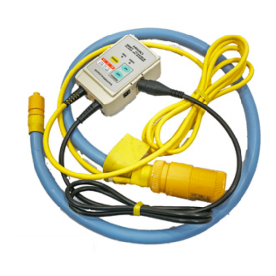
Parts Names

Measurement Procedures

|
NOTE
Attach the clamp around only one conductor. Single-phase (2-wire) or three-phase (3-wire) cables clamped together will not produce any reading.


Engage the BNC connector grooves with the connector-guide projections, and turn the connector clockwise to lock the components.
To remove the BNC connector: Turn the connector counterclockwise and pull it out.
Remove the sensor while pressing both sides of the sensor connector as shown in the illustration.
If the sensor connector does not move, check whether the LOCK has been released.
Hold only one conductor at the clamp center with the current direction toward the load side.
Securely push the tip of the sensor into the sensor connector.

If necessary, lock the sensor connector.

To LOCK, turn the sensor in the direction of the LOCK mark until you hear a click.
Turn ON the power to the circuit box. (default setting: 5000 A) Select the appropriate range (500/5000 A) using the RANGE button. If the power goes off and then on again, the range will always reset to 5000 A.
NOTE
When using the AC adapter for continuous monitoring, we recommend that you also use batteries to prevent interruptions due to instantaneous power outages.
(If the AC adapter is not used together with batteries, the power goes OFF following an instantaneous power outage.)
Replacing the Batteries

| |
|
NOTE
- After use, always turn OFF the power.
- If the power does not go ON after replacing batteries, the fuse maybe blown. In this case, do not attempt to replace the fuse or repair the product. Contact your dealer or a HIOKI representative.
- When using an AC adapter, always use the optional 9445-02/03AC Adapter.
Necessary tool:
Precision Phillips screwdriver

- Turn OFF the power to the circuit box.
- Turn the circuit box over and use a Phillips screwdriver to remove the two retaining screws from the lower case.
- Remove the upper case and mount four new LR03 alkaline batteries. Make sure the polarity is correct.
- Mount the upper case and tighten the retaining screws.
Clamp Sensor Connector Lock System

NOTE
- If you pull out hard the lock-ing part of the Clamp sensor connector, the locking part might be dislodged.
- If this happens, reconnect the connector so that the current direction indicator faces inside as shown in the illustration. If the indicator is faced outside, the current direction indicator will indicate the opposite direction to the actual measuring cur-
Introduction
To obtain maximum performance from the product, please read this manual first, and keep it handy for future reference.
Overview
The 9667 Flexible Clamp On Sensor measures large currents of up to 5000 A AC.
The hollow core coil makes the sensor unit highly flexible, allowing it to be used for clamping in narrow spaces with crowded wiring. This is a feature not seen in sensors that use conventional cores.
Inspection and Maintenance
Initial Inspection
When you receive the product, inspect it carefully to ensure that no damage occurred during shipping. If damage is evident, or if it fails to operate according to the specifications, contact your dealer or Hioki representative.
Preliminary Checks
- Before using the product the first time, verify that it operates normally to ensure that the no damage occurred during storage or shipping. If you find any damage, contact your dealer or Hioki representative.
- Before using the product, make sure that the insulation on the cables is undamaged and that no bare conductors are improperly exposed. Using the product in such conditions could cause an electric shock, so contact your dealer or Hioki representative for repair.
Maintenance and Service
- To clean the product, wipe it gently with a soft cloth moistened with water or mild detergent. Never use solvents such as benzene, alcohol, acetone, ether, ketones, thinners or gasoline, as they can deform and discolor the case.
- If the product seems to be malfunctioning, contact your dealer or Hioki representative.
Specifications
(Accuracy guaranteed for one year at 23±5°C (73±9°F), 80%RH or less)
| Rated primary current | 5000 to 500 A AC/ 500 to 50 A AC |
| Output voltage | 500 mVAC f.s. |
| Amplitude accuracy | ±2% rdg.±1.5 mV (at 45 Hz to 66 Hz, at sensor center) |
| Frequency band | 10 Hz to 20 kHz (amplitude error: within ±3dB) |
| Phase accuracy | Within ±1° (at 45 Hz to 66 Hz) |
| Temperature characteristic | ±2% rdg./°C |
| Effect of conductor position | Within ±3% (deviation from center) |
| Effect of external electromagnetic field | 5 A equivalent, 7.5 A max. (in an external electromagnetic field of 400 A/m |
| Maximum input current | 10,000 A continuous (at 45 to 66 Hz) |
| Dielectric strength | 6880 Vrms for 15 seconds (between circuit and sensor, at 50/60 Hz) |
| Maximum rated voltage to earth | 1000 VACrms or less |
| Operating temperature & humidity | 0 to 40°C (32 to 104°F), 80%RH or less (non-condensating) |
| Temperature of conductor to be measured | 50°C or less (122°F or less) |
| Storage temperature & humidity | -10 to 50°C (14 to 122°F), 80%RH or less (non-condensating) |
| Operating environment | Indoors, altitude up to 2000 m (6562-ft.) |
| Applicable Standards | (Safety) EN61010 Measurement Category III, Pollution Degree 2 (Anticipated Transient Overvoltage: 8000 V) (EMC) EN61326 EN61000-3-2 EN61000-3-3 |
| Power supply | LR03 alkaline battery x 4 (1.5 VDC x 4) or 9445-02/03 AC ADAPTER (9 VDC) (option) (Voltage fluctuations of ±10% from the rated supply voltage are taken into account.) |
| Maximum rated power | 35 mVA (using batteries), 50 mVA (using AC adapter) |
| Battery life | Approx. 7.5 days (continuous) |
| Output impedance | 100 Ω or less |
| Measurable conductor diameter | φ254 mm or less |
| Cable length | Approx. 2 m (78.74") (between sensor and circuit), approx. 1m (39.37") (output cord) |
| Dimensions | Approx. 910 mm (35.83")(when sensor unit is open) Approx. 57.5W x 86.5H x 30D mm (2.26"W x 3.41"H x 1.18"D) (Circuit box) |
| Mass | Approx. 450 g (15.9 oz.) (including batteries) |
| Accessories | Instruction Manual, LR03 alkaline battery x 4 |
| Options | 9445-02 AC Adapter 9445-03 AC Adapter |
f.s.: maximum display value or scale length (This is usually the maximum value of the currently selected range.)
rdg.: reading value (The value currently being measured and indicated on the measuring product)
Safety
Follow these precautions to ensure safe operation and to obtain the full benefits of the various functions.
 This product is designed to conform to IEC 61010 Safety Standards, and has been thoroughly tested for safety prior to shipment. However, mishandling during use could result in injury or death, as well as damage to the product. Using the instrument/ device/ product in a way not described in this manual may negate the provided safety features. Be certain that you understand the instructions and precautions in the manual before use. We disclaim any responsibility for accidents or injuries not resulting directly from product defects. |
Measurement categories
This product complies with CATIII (1000 V) safety requirements.
To ensure safe operation of measurement products, IEC 61010 establishes safety standards for various electrical environments, categorized as CAT II to CAT IV, and called measurement categories.
CAT II: Primary electrical circuits in equipment connected to an AC electrical outlet by a power cord (portable tools, household appliances, etc.) CAT II covers directly measuring electrical outlet receptacles.
CAT III: Primary electrical circuits of heavy equipment (fixed installations) connected directly to the distribution panel, and feeders from the distribution panel to outlets.
CAT IV: The circuit from the service drop to the service entrance, and to the power meter and primary overcurrent protection device (distribution panel).

Using a measurement product in an environment designated with a higher-numbered category than that for which the product is rated could result in a severe accident, and must be carefully avoided.
Use of a measurement instrument that is not CAT-rated in CAT II to CAT IV measurement applications could result in a severe accident, and must be carefully avoided.
Safety Symbol
 | In the manual, the symbol indicates particularly important information that the user should read before using the product. The symbol printed on the product indicates that the user should refer to a corresponding topic in the manual (marked with the symbol) before using the relevant function. |
 | Indicates a double-insulated device. |
 | Indicates AC (Alternating Current). |
 | Indicates DC (Direct Current). |
 | Wear appropriate protective insulation (insulating rubber gloves and boots, helmet and etc.) when connecting and disconnecting from live electric circuits. |
The following symbols in this manual indicate the relative importance of cautions and warnings.
Indicates that incorrect operation presents an extreme hazard that could result in serious injury or death to the user.
Indicates that incorrect operation presents a significant hazard that could result in serious injury or death to the user.
Indicates that incorrect operation presents a possibility of injury to the user or damage to the product
NOTE
Advisory items related to performance or correct operation of the product.
Usage Notes
This manual contains information and warnings essential for safe operation of the product and for maintaining it in safe operating condition. Before using the product, be sure to carefully read the following safety notes.

| ||
| ||
|
NOTE
Accurate measurement may be impossible in the presence of strong magnetic fields, such as near transformers and high-current conductors, or in the presence of strong electromagnetic fields such as near radio transmitters.
Headquarters
81 Koizumi, Ueda, Nagano 386-1192, Japan
TEL +81-268-28-0562 FAX +81-268-28-0568
E-mail: os-com@hioki.co.jp URL http://www.hioki.com/
(International Sales and Marketing Department)
For regional contact information, please go to our website at http://www.hioki.com/
The Declaration of Conformity for products that comply to CE mark requirements may be found on the HIOKI website.

Documents / Resources
References
Download manual
Here you can download full pdf version of manual, it may contain additional safety instructions, warranty information, FCC rules, etc.
Advertisement


Need help?
Do you have a question about the 9667 and is the answer not in the manual?
Questions and answers