
Subscribe to Our Youtube Channel
Related Manuals for Hioki 9279


Summary of Contents for Hioki 9279
- Page 1 取扱説明書 Instruction Manual 9279 ユニバーサル クランプオンCT UNIVERSAL CLAMP ON CT 2004年3月 発行 改訂3版 March 2004 Revised edition 3 9279A981-03 04-03H...
-
Page 3: Table Of Contents
目 次 はじめに 点検 使用前の確認 安全について ご使用にあたっての注意 第 1 章 概要 1.1 製品の概要 1.2 各部の名称 第 2 章 測定方法 2.1 測定方法 2.2 消磁について 第 3 章 仕様 第 4 章 保守・サービス 4.1 本器のクリーニング 4.2 サービス... -
Page 5: はじめに
__________________________________________________ はじめに 9279 ユニバーサルクランプオ このたびは、HIOKI ン CT をご選定いただき、誠にありがとうございま す。この製品を十分にご活用いただき、末長くご使用 いただくためにも、取扱説明書はていねいに扱い、い つもお手元に置いてご使用ください。 点検 本器がお手元に届きましたら、輸送中において異常ま たは破損がないかを点検してからご使用ください。 特に付属品に注意してください。 万一、破損あるいは仕様どおり動作しない場合は、お 買上店(代理店)または最寄りの営業所にご連絡くだ さい。 使用前の確認 ・使用前には、保存や輸送による故障がないか、点検 と動作確認をしてから使用してください。故障を確 認した場合は、お買上店(代理店)か最寄りの営業 所にご連絡ください。 ・ケーブルの被覆が破れたり、金属が露出していない か、使用する前に確認してください。損傷がある場 合は、感電事故になるので、お買上店(代理店)か 最寄りの営業所にご連絡ください。 _____________________________________________... -
Page 6: 安全について
__________________________________________________ 安全について 危 険 この機器は IEC348 安全規格に従って、設計され、試験し、 安全な状態で出荷されています。測定方法を間違えると人 身事故や機器の故障につながる可能性があります。取扱説 明書を熟読し、十分に内容を理解してから操作してくださ い。万一事故があっても、弊社製品が原因である場合以外 は責任を負いかねます。 安全記号 この取扱説明書には本器を安全に操作し、安全な状態 に保つのに要する情報や注意事項が記載されています。 本器を使用する前に下記の安全に関する事項をよくお 読みください。 ・使用者は、機器上に表示されている マークのところ について、取扱説明書の マークの該当箇所を参照 し、機器の操作をしてください。 ・使用者は、取扱説明書内の マ ークのあるところは、 必ず読み注意する必要があることを示します。 取扱説明書の注意事項には、重要度に応じて以下の 表記がされています。 操作や取扱いを誤ると、使用者が死亡または重傷に 危 険 つながる危険性が極めて高いことを意味します。 操作や取扱いを誤ると、使用者が死亡または重傷に 警 告 つながる可能性があることを意味します。 操作や取扱いを誤ると、使用者が傷害を負う場合、 注 意 または機器を損傷する可能性があることを意味します。 製品性能および操作上でのアドバイス的なことを... - Page 7 __________________________________________________ 確度について 弊社では測定値の限界誤差を、次に示す f.s.(フルス ケール) 、rdg.(リーディング)に対する値として定義 しています。 f.s. (最大表示値、目盛長) 最大表示値または、目盛長を表します。 一般的には、現在使用中のレンジを表します。 rdg. (読み値、表示値、指示値) 現在測定中の値、測定器が現在指示している値を 表します。 _____________________________________________...
-
Page 8: ご使用にあたっての注意
__________________________________________________ ご使用にあたっての注意 本器を安全にご使用いただくために、また機能を十二分 にご活用いただくために、下記の注意事項をお守りくだ さるようお願いいたします。 危 険 ・短絡事故や人身事故を避けるため、ユニバーサルクランプ オン CT は AC600 Vrms 以下の電路で使用してください。 また裸導体には使用しないでください。 ・ユニバーサルクランプオン CT は、必ずブレーカの二次側 に接続してください。ブレーカの二次側は、万一短絡があ っても、ブレーカにて保護します。一次側は、電流容量が 大きく、万一短絡事故が発生した場合、損傷が大きくなる ので、測定しないでください。 警 告 ・本器をぬらしたり、ぬれた手で測定しないでください。感 電事故の原因になります。 ・活線で測定するので、感電事故を防ぐため、労働安全衛生 規則に定められているように、電気用ゴム手袋、電気用ゴ ム長靴、安全帽等の絶縁保護具を着用してください。 _____________________________________________... - Page 9 __________________________________________________ 注 意 ・測定範囲を超える電流を長時間入力しないでください。本 器を破損する恐れがあります。 ・直射日光や高温、多湿、結露するような環境下での、保存 や使用はしないでください。変形、絶縁劣化を起こし、仕 様を満足しなくなります。 ・本器の損傷を防ぐため、運搬および取扱いの際は振動、衝 撃を避けてください。特に、落下などによる衝撃に注意し てください。本器を破損します。 ・コア部つき合わせ面にゴミなどが付着した場合は、測定に 影響がでますので柔らかい布で軽くふき取ってください。 ・コード類の被覆に損傷を与えないため、踏んだり挟んだり しないでください。 ・コードが溶けると金属部が露出し危険です。発熱部等に触 れないようにしてください。 ・断線による故障を防ぐため、ケーブル を折ったり引っ張っ たりしないでください。 ・本器の使用環境および設置場所は使用温湿度範囲 0℃〜40 ℃の屋内ですが、安全性を損なわないで-10℃までの範囲 で使用できます。 ・高周波大電流を測定するとき、コアが発熱する場合があり ます。最大許容入力範囲を超えないように注意してくださ い。 「第 3 章 仕様」のグラフをご参照ください。 トランスや大電流路など強磁界の発生している近く、 注 記 また無線機など強電界の発生している近くでは、正確 な測定ができない場合があります。 _____________________________________________...
- Page 10 __________________________________________________ _____________________________________________...
-
Page 11: 第 1 章 概要
__________________________________________________ 第 1 章 概要 1.1 製品の概要 本器は 500 A 定格の AC/DC 電流対応のセンサとして 開発され、電力ラインを切り離すことなく、活線の状 態で交流・直流電流を測定できます。 また、良好な周波数特性(振幅、位相) 、良好な温度特 性(感度、オフセット) 、耐電圧を有しており、操作、 接続が簡単であるので、多方面での電流、電力測定に ご使用いただけます。 _____________________________________________ 第 1 章 概要... -
Page 12: 各部の名称
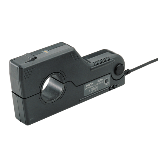
__________________________________________________ 1.2 各部の名称 レバー 電流方向表示マーク クランプコア DMAG スイッチ ケーブル 出力コネクタ _____________________________________________ 第 1 章 概要... -
Page 13: 第 2 章 測定方法
__________________________________________________ 第 2 章 測定方法 2.1 測定方法 注 意 ・断線防止のため、出力コネクタを引き抜くときは、差込部 分(ケーブル以外)を持って抜いてください。 ・接続機器の電源が入った状態、または測定導体をクランプ した状態で、コネクタの抜差しをしないでください。本体 およびセンサの故障の原因になります。 ・連続最大入力範囲は測定時の自己発熱による温度上昇から 定めた値です。これを超える電流を入力しないでくださ い。本器を損傷する恐れがあります。 ・連続最大許容入力範囲は測定電流の周波数によって異なり ます。 「第 3 章 仕様」のグラフをご参照ください。 ・測定電流が小さい場合、導体を複数巻くことにより相 注 記 対的に感度をあげることができます。導体を 10 回巻 きした場合、測定電流の 10 倍の信号が出力されま す。ただし、巻き線の直径は 20 cm 以上で放射状に なるようにしてください。 ・この製品の信号出力回路は直列に抵抗が挿入されてい ます。そのため、出力信号を直接測定する場合は、入 力抵抗の十分大きな測定機器を使用するようにしてく ださい。... - Page 14 __________________________________________________ 1. クランプ部が開いている場合は閉 じます。 2. 接続機器の電源が OFF になってい るか確認します。 3. クランプオン CT の出力コネクタを 接続します。 4. 接続機器の電源を ON にします。 5. DMAG スイッチを押して消磁しま す。 ( 「2.2 消磁について」をご覧く ださい) 6. レバーを軽く押して両手でクラン プ先端を開きます。 7. センサ部先端に表示されている電 流方向マークの矢印の方向が被測 電流方向マーク 定電流の流れる方向と一致するよ うに被測定導体をクランプしてく ださい。 被測定導体がクランプ窓部の中央 になるようにしてください。 ・導体は必ず一本だけクランプしてください。単相(2 注 記 本)...
-
Page 15: 消磁について
__________________________________________________ 2.2 消磁について 直流電流測定や交流電流測定時の突入電流などを測定 した後では、クランプに入力がない状態でも微小電圧 が出力されます。これは、クランプに用いているコア の特性によるもので、コア内に磁気が残るためです。 この残留磁気は測定誤差になりますが、クランプに入 力がない状態で DMAG スイッチを押すことにより、残 留磁気を取り去ることができます。 ・電源投入時、DMAG スイッチを一度押してください。 注 記 ・入力中に DMAG スイッチを押しても消磁はできませ ん。 ・消磁はクランプ部が閉じた状態で行ってください。 ・消磁動作は約 3 秒ほどかかります。 ・クランプに過大な電流が入力された後、一回の消磁動 作で完全に残留磁気を取り除けない場合は、一度クラ ンプを開けた状態で DMAG スイッチを押し、さらに 閉じた状態で再度 DMAG スイッチを押してください。 ・クランプを閉じる場合、突き合わせ面に衝撃が加わる と、オフセットが出力される場合があります。この場 合、クランプに入力が無い状態で DMAG スイッチを 押すと、正常状態に戻ります。 ・直流電流測定の場合、連続最大許容入力以上の入力が されると、誤動作する場合があります。この場合もク ランプに入力がない状態で... - Page 16 __________________________________________________ _____________________________________________ 第 2 章 測定方法...
-
Page 17: 第 3 章 仕様
__________________________________________________ 第 3 章 仕様 定格電流(AC/DC) 500 A f.s. 出力電圧(AC/DC) 2 V/500 A 650 Arms (920 Apeak) 最大許容入力範囲 (DC〜3kHz にて) 0.001 mΩ以下 入力抵抗(DC) 50 Ω 出力抵抗 DC および 45〜66 Hz、ウォーミングアップ 30 基本確度 23℃±3℃ 分以上において消磁後 振幅:±0.5% rdg. ±0.05% f.s. 位相:±0.2°以内(ただし DC は規定なし) 1 年間... - Page 18 __________________________________________________ AC2,200 Vrms 1 分間(電気回路−ケース間, 電 耐電圧 気回路−コア間) DC500 V 100 MΩ以上(電気回路−ケース間, 絶縁抵抗 電気回路−コア間) AC600 Vrms(850 Vpeak)絶縁導体 対地間最大定格 電圧 φ40 mm 以下 測定可能導体 ±12 V〜±15 V(確度保証内、ただしトラッ 電源電圧 キング) ±90 mA(無負荷時) 電源容量 (±12 V 時) ±250 mA(定格入力時) Max.7.2 W(定格入力時) 消費電力 約 220 W×103 H×43.5 D mm(突起物含まず) 外形寸法・質量...
- Page 19 ④ Vout (2 V f.s./定格入力) 出力 ⑤ 出力 ⑥ 消磁信号 ⑦ 識別信号 ⑧ 識別信号 ⑨ シールド ⑩ 出力コネクタのピン配列 9279 GND に接続 適合レセプタクル RM515ERB-10SD(ヒロセ 注 意 ・使用電源の容量は、±とも 0.5 A 以上必要です。 ・電源電圧の接続を間違えると、内部回路が破壊される場合 がありますので注意してください。 ・消磁は、⑦ピンを GND と短絡後、開放することで動作し ます。 _____________________________________________ 第 3 章 仕様...
- Page 20 __________________________________________________ 周波数 9279 最大許容入力範囲(連続) _____________________________________________ 第 3 章 仕様...
-
Page 21: 第 4 章 保守・サービス
__________________________________________________ 第 4 章 保守・サービス 4.1 本器のクリーニング 本器の汚れをとるときは、柔らかい布に水か中性洗剤 を少量含ませて、軽くふいてください。ベンジン、ア ルコール、アセトン、エーテル、ケトン、シンナー、 ガソリン系を含む洗剤は絶対に使用しないでください。 変形、変色することがあります。 4.2 サービス ・故障と思われるときは、お買上店(代理店)か最寄 りの営業所にご連絡ください。輸送中に破損しない ように梱包し、故障内容も書き添えてください。輸 送中の破損については保証しかねます。 ・本器の確度維持あるいは確認には、定期的な校正が 必要です。 修理・校正業務のご用命は、 「日置エンジニアリング サービス(株) 」までお願いいたします。 (TEL 0268-28-0823、FAX 0268-28-0824) _____________________________________________ 第 4 章 保守・サービス... - Page 22 __________________________________________________ _____________________________________________ 第 4 章 保守・サービス...
- Page 23 保 証 書 形名 製造番号 保証期間 9279 購入日 年 月より1年間 本製品は、弊社の厳密なる検査を経て合格した製品をお届けした物です。 万一ご使用中に故障が発生した場合は、お買い求め先に依頼してください。 本書の記載内容で無償修理をさせていただきます。 (保証期間は購入日より1年間です。購入日が不明の場合は、製品の製造月 から1年を目安とします) 依頼の際は、本書を提示してください。 お客様 ご住所: 〒 ご芳名: *お客様へのお願い ・保証書の再発行はいたしませんので、大切に保管してください。 ・「形名、製造番号、購入日」およびお客様「ご住所、ご芳名」は恐れ入 りますが、お客様にて記入していただきますようお願いいたします。 1.取扱説明書・本体注意ラベル (刻印を含む) などの注意事項にしたがった正常な使用 状態で保証期間内に故障した場合には、無償修理いたします。 2.保証期間内でも、次の場合には有償修理となります。 −1.本書の提示がない場合。 −2.取扱説明書に基づかない不適当な取扱い、 または使用上の誤りによる故障およ び損傷。 −3.不当な修理や改造による故障および損傷。 −4.お買い上げ後の輸送や落とされた場合などによる故障および損傷。 −5.外観上の変化(筐体のキズ)の場合。 −6.火災・公害・異常電圧および地震・雷・風水害その他天災地変など、 外部に原 因がある故障および損傷。 −7.消耗部品(乾電池等)が消耗し取換えを要する場合。 −8.その他弊社の責任とみなされない故障。 3.本保証書は日本国内のみ有効です。 (This warranty is valid only in Japan.) サービス記録...
- Page 24 外国代理店については HIOKI ホームページを ご覧いただくか、最寄りの営業所または本社 外国主要販売ネットワーク 販売企画課までお問い合わせください。 URL http: //www.hioki.co.jp/ HIOKI USA CORPORATION 6 Corporate Drive, Cranbury, NJ 08512 USA TEL +1-609-409-9109 FAX +1-609-409-9108 E-MAIL hioki@hiokiusa.com...
- Page 25 HIOKI 9279 ユニバーサルクランプオン CT 取扱説明書 2004 年 3 月 改訂 3 版 発 行 年 月 編 集 ・ 発 行 日置電機株式会社 開発支援課 問 合 せ 先 日置電機株式会社 販売企画課 〒386-1192 長野県上田市小泉 81 0120-72-0560 TEL: 0268-28-0560 FAX: 0268-28-0579 E-mail: info@hioki.co.jp URL http: //www.hioki.co.jp/ Printed in J a p a n 9279A981-03 ・本書の内容に関しては万全を期していますが、ご不明な点や...
- Page 27 9279 UNIVERSAL CLAMP ON CT INSTRUCTION MANUAL...
- Page 29 Contents Introduction Inspection Preliminary Checks Safety Notes Notes on Use Chapter 1 Overview 1.1 Product Overview 1.2 Names of Parts Chapter 2 Measurement Procedure 2.1 Measurement Procedure 2.2 Demagnetizing (DMAG) Chapter 3 Specification Chapter 4 Maintenance and Service 4.1 Maintenance 4.2 Service...
-
Page 31: Introduction
__________________________________________________ Introduction Thank you for purchasing the HIOKI "9279 UNIVERSAL CLAMP ON CT". To obtain maximum performance from the product, please read this manual first, and keep it handy for future reference. Inspection When you receive the product, inspect it carefully to ensure that no damage occurred during shipping. -
Page 32: Safety Notes
__________________________________________________ Safety Notes DANGER This product is designed to conform to IEC 348 Safety Standards, and has been thoroughly tested for safety prior to shipment. However, mishandling during use could result in injury or death, as well as damage to the product. Be certain that you understand the instructions and precautions in the manual before use. - Page 33 __________________________________________________ The following symbols in this manual indicate the relative importance of cautions and warnings. Indicates that incorrect operation presents an extreme hazard that could result in serious DANGER injury or death to the user. Indicates that incorrect operation presents a significant hazard that could result in serious WARNING injury or death to the user.
- Page 34 __________________________________________________ Accuracy The specifications in this manual include figures for "measurement accuracy" when referring to digital measuring instruments, and for "measurement tolerance" when referring to analog instruments. f.s. (maximum display or scale value, or length of scale) Signifies the maximum display (scale) value or the length of the scale (in cases where the scale consists of unequal increments or where the maximum value cannot be defined).
-
Page 35: Notes On Use
__________________________________________________ Notes on Use Follow these precautions to ensure safe operation and to obtain the full benefits of the various functions. DANGER To avoid short circuits and potentially life- threatening hazards, never attach the UNIVERSAL CLAMP ON CT to a circuit that operates at more than the 600 Vrms, or over bare conductors. - Page 36 __________________________________________________ CAUTION Note that the product may be damaged if current exceeding the selected measurement range is applied for a long time Do not store or use the product where it could be exposed to direct sunlight, high temperature or humidity, or condensation.
- Page 37 __________________________________________________ Accurate measurement may be impossible in NOTE the presence of strong magnetic fields, such as near transformers and high-current conductors, or in the presence of strong electromagnetic fields such as near radio transmitters. _____________________________________________...
- Page 38 __________________________________________________ _____________________________________________...
-
Page 39: Chapter 1 Overview
__________________________________________________ Chapter 1 Overview 1.1 Product Overview The 9279 was developed for to provide a 500 A clamp sensor corresponding to AC/DC current. The 9279 makes it possible to measure AC/DC current in live power lines without cutting into the lines. The sensor features good frequency... -
Page 40: Names Of Parts
__________________________________________________ 1.2 Names of Parts Lever Current direction indication Clamp core DMAG switch Cable Output connector _____________________________________________ Chapter 1 Overview... -
Page 41: Chapter 2 Measurement Procedure
__________________________________________________ Chapter 2 Measurement Procedure 2.1 Measurement Procedure CAUTION To avoid damaging the output cable, grasp the connector, not the cable, when unplugging the cable. To prevent damage to the product and sensor, never connect or disconnect a sensor while the power is on. The maximum continuous input range is based on heat that is internally generated during measurement. - Page 42 __________________________________________________ To measure small current levels, multiple NOTE windings may be used to increase the relative sensitivity. 10 windings multiplies the measured current by about a factor of 10. However, in this case the diameter of the winding should be 20 cm or more, and radial. This product has a resistance in series with the signal output circuits.
- Page 43 __________________________________________________ 1. Close the clamp jaws when the clamp jaws are opened. 2. Make sure that the unit's power switch is OFF. 3. Connect the clamp-on CT connector to the unit. 4. Turning the power on the unit. 5. Press the DMAG switch to magnetize.
-
Page 44: Demagnetizing (Dmag)
DMAG switch with no input on the clamp, to return to normal. If it does not return to normal condition, or even pressing DMAG, the magnetic is remained in the core, contact your dealer or Hioki representative. _____________________________________________ Chapter 2 Measurement Procedure... -
Page 45: Chapter 3 Specification
__________________________________________________ Chapter 3 Specification Rated current 500 A f.s. (AC/DC) Output voltage 2 V/500 A (AC/DC) The maximum 650 Arms (920 Apeak) permissible input range (DC to 3 kHz) Input resistance (DC) 0.001 mΩ or less 50 Ω Output resistance Basic accuracy DC and 45 Hz to 66 Hz, 30 min or 23 3... - Page 46 __________________________________________________ Dielectric strength 2200 Vrms for 1 min. (between electric circuit and case, between electric circuit and core) Insulation resistance 500 V DC 100 MΩ or more (between electric circuit and case, between electric circuit and core) Maximum rated 600 Vrms (850 Vpeak) insulated voltage to earth conductor Diameter of...
- Page 47 ID1 8 Identifying signal ID2 9 Identifying signal Shield (cable) Output connector pin array 9279 Connect to GND Mating receptacle RM515ERB-10SD (HIROSE) CAUTION Be careful to avoid connecting voltage improperly, as the internal circuitry may be destroyed. The capacity of the power supply is at least 0.5 A.
- Page 48 __________________________________________________ Frequency 9279 The maximum permissible input range (continuous) _____________________________________________ Chapter 3 Specification...
-
Page 49: Chapter 4 Maintenance And Service
Hioki representative. Pack the product carefully so that it will not be damaged during shipment, and include a detailed written description of the problem. Hioki cannot be responsible for damage that occurs during shipment. _____________________________________________ Chapter 4 Maintenance and Service... - Page 50 __________________________________________________ _____________________________________________ Chapter 4 Maintenance and Service...
- Page 51 HIOKI 9279 UNIVERSAL CLAMP ON CT Instruction Manual Publication date: March 2004 Revised edition 3 Edited and published by HIOKI E.E. CORPORATION Technical Sales Support Section All inquiries to International Sales and Marketing Department 81 Koizumi, Ueda, Nagano, 386-1192, Japan TEL: +81-268-28-0562 / FAX: +81-268-28-0568 E-mail: os-com@hioki.co.jp...
- Page 52 9279A981-03 04-03H Printed on recycled paper...
Need help?
Do you have a question about the 9279 and is the answer not in the manual?
Questions and answers