Advertisement
Overview
With this device, you can use the Model 9270, 9271, 9272, 9277, 9278, 9279, 9709, 9272-10, CT6862, CT6863 current sensors as separate units. It is equipped with a high-performance sensor for easy current waveform measurement.
Use it as input unit for various current measurement applications combined with a recorder, oscilloscope, voltmeter, etc.
Initial Inspection
When you receive the device, inspect it carefully to ensure that no damage occurred during shipping. In particular, check the accessories, panel switches, and connectors. If damage is evident, or if it fails to operate according to the specifications, contact your dealer or Hioki representative.
Maintenance and Service
- To clean the device, wipe it gently with a soft cloth moistenedwith water or mild detergent. Never use solvents such as benzene, alcohol, acetone, ether, ketones, thinners or gasoline, as they can deform and discolor the case.
- If the device seems to be malfunctioning, confirm that thebatteries are not discharged, and that the test leads, probes and fuse are not open circuited before contacting your dealer or Hioki representative.
NOTE
Pack the device so that it will not sustain damage during shipping, and include a description of existing damage. We cannot accept responsibility for damage incurred during shipping.
Usage Notes
Follow these precautions to ensure safe operation and to obtain the full benefits of the various functions.

- Be sure to observe all operating precautions for thewaveform monitoring instrument (oscilloscope or recorder) and other measurement instruments to which the CURRENT SENSOR (refer to Specifications) is connected using with this device.
- When using a measurement instrument that does notprovide isolation between its input terminals and chassis or other input terminals, please pay attention to the following points.
If a signal is applied to an input terminal other than that to which the CURRENT SENSOR is connected, do not connect the ground-side terminal to any non-ground potential. Otherwise, short-circuit current will flow through the CURRENT SENSOR or this device from the ground terminal, which could cause an electrical accident or damage.

Never connect the tester as shown in the figure.


- Before turning the device on, make sure the supply voltage matches that indicated on the its power connector. Connection to an improper supply voltage may damage the device and present an electrical hazard.
- Use only the supplied Model 9418-15 AC ADAPTER. AC adapter input voltage range is 100 to 240 VAC (with ±10% stability) at 50/60 Hz. To avoid electrical hazards and damage to the device, do not apply voltage outside of this range.

- Be careful to avoid connecting voltage improperly, as the internal circuitry may be destroyed.
- Turn off the power before disconnecting the power cord.
- To avoid damage to the device, do not short the output terminal and do not input voltage to the output terminal.
- Because ± 12 V is output from the connector on the equipment to provide power to the sensor, do not plug anything into this connector except for the sensor connector.
- To prevent damage to the connected instruments and the sensor, never connect or disconnect a sensor while the power is on, or while the sensor is clamped around a conductor.
- To avoid damaging the power cord, grasp the plug, not the cord, when unplugging it from the power outlet.
- When the power is turned off, do not apply voltage or current to the clamp sensor. Doing so may damage the device.
- To avoid damage to the device, protect it from physical shock when transporting and handling. Be especially careful to avoid physical shock from dropping.
- Do not store or use the device where it could be exposed to direct sunlight, high temperature or humidity, or condensation. Under such conditions, the device may be damaged and insulation may deteriorate so that it no longer meets specifications.
- Avoid stepping on or pinching cables, which could damage the cable insulation.
- Keep the cables well away from heat sources, as bare conductors could be exposed if the insulation melts.
- Use the 9217 CONNECTION CORD (resin) when connecting to insulated BNC terminal, and the 9165 CONNECTION CORD (metal) when connecting to metallic BNC terminal. If you connect metal BNC cable to insulated BNC terminal, the insulated BNC terminal can be damaged and the connection equipment may be damaged.
NOTE
- Correct measurement may be impossible in the presence of strong magnetic fields, such as near transformers and highcurrent conductors, or in the presence of strong electromagnetic fields such as near radio transmitters.
- This device may cause interference if used in residential areas. Such use must be avoided unless the user takes special measures to reduce electromagnetic emissions to prevent interference to the reception of radio and television broadcasts.
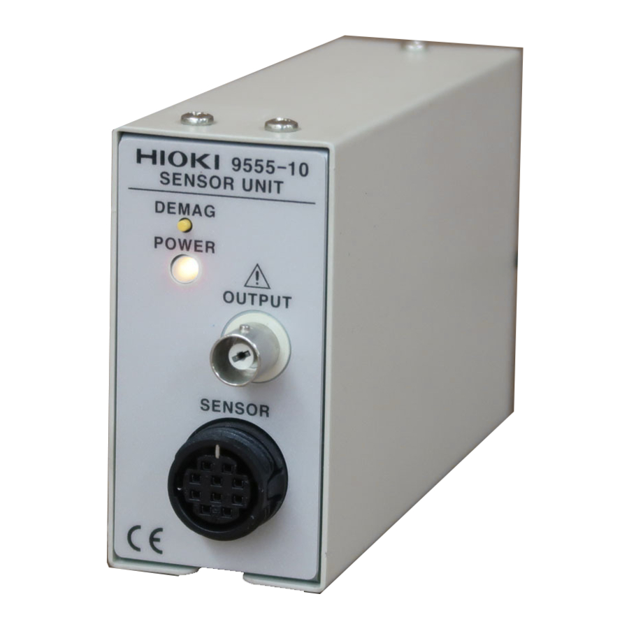
Names of Parts

Measurement Procedure
Preliminary Checks
Before using the device the first time, verify that it operates normally to ensure that the no damage occurred during storage or shipping. If you find any damage, contact your dealer or Hioki representative.
- Confirm that the power switch is OFF, then connect the AC ADAPTER and the power cord. Be sure to run the AC ADAPTER cord through the locking clamp as shown in the diagram left to prevent disconnection.
![]()
- Connect the clamp sensor to the sensor connector.
![]()
- Turn the power switch ON and confirm that the power monitor lights.

When using 9277, 9278 or 9279, you can enact demagnetization by pressing DEMAG SW. - Clamp the subject conductor and perform the measurement.
![]()


NOTE
- Use a measuring instrument with an input resistance of 1 M or more.
- If the power monitor does not light when the power switch isturned on, it is likely the device has damaged.
- Also refer to the clamp sensor instruction manual.
Specifications
General Specifications
| Operating environment | Indoors, Up to 2000 m (6562ft) ASL |
| Operating temperature and humidity | 0°C to 40°C (32 to 104°F), 80%RH max. (no condensation) |
| Storage temperature and humidity | -10°C to 50°C (14 to 122°F), 80%RH max. (no condensation) |
| Applicable Standards | EN61010 Pollution degree 2 EN61326 Class A EN61000-3-2 EN61000-3-3 |
| Accessories | Instruction manual Model 9418-15 AC ADAPTER (with a power cord) Rated supply voltage: AC100 to 240 V (Voltage fluctuations of ±10% from the rated supply voltage are taken into account.) Rated supply frequency: 50/60 Hz Rated output voltage: DC 12 V |
Specifications
| Applicable current sensors | Model 9270, 9271,9272, 9277, 9278, 9279, 9709, 9272-10,CT6862,CT6862-10,CT6863,CT6863-10, CT6865 |
| Output terminal | BNC terminal Accuracy and other characteristics depend on the connected sensor. |
| Output supply voltage | ±12 V ±0.5 V, 0.5 Amax |
| Rated supply voltage | +10 V to +30 V (The supplied AC ADAPTER supplies +12 V.) |
| Maximum rated power | 20 VA |
| Dimensions (Not including protrusions) | Approx. 42W×82H×132D mm Approx. 1.65"W×3.24"H×5.20"D |
| Mass | Approx. 600 g (21.2 oz.) |
| SENSOR connector | RM515ERB-10SD(HIROSE ELECTRIC CO., LTD.) Connector Pin Configuration
Compatible Connector |
| SW for DEMAG | Pressing SW shorts the circuit from 7-10. |

Application Example
If the distance between the location of the current to be measured and the measuring instrument is greater than the length of the CURRENT SENSOR cable, measurement is possible by extending from the 9555-10 analog output. Note that there may be effects such as noise.

Headquarters
81 Koizumi, Ueda, Nagano 386-1192, Japan
TEL +81-268-28-0562
FAX +81-268-28-0568
E-mail: os-com@hioki.co.jp
URL http://www.hioki.com/
(International Sales and Marketing Department)
For regional contact information, please go to our website at
http://www.hioki.com.

Documents / Resources
References
Download manual
Here you can download full pdf version of manual, it may contain additional safety instructions, warranty information, FCC rules, etc.
Advertisement


Need help?
Do you have a question about the 9555-10 and is the answer not in the manual?
Questions and answers