Table of Contents
Advertisement
Quick Links
SP7001
SP7002
NON-CONTACT CAN SENSOR
SP7100
SP7150
CAN INTERFACE
SP9200
SP9250
SIGNAL PROBE
Be sure to read this manual before using the instrument.
When using the instrument for the
first time
Part Names and Functions
Preparing Before Use
Functionality
July 2021 Revised edition 1
SP7001A961-01 21-07H
p.10
p.15
p.27
HIOKI SP7001A961-01
Instruction Manual
Troubleshooting
Maintenance and Service
p.7
p.43
EN
Advertisement
Table of Contents

Related Manuals for Hioki SP7150


Summary of Contents for Hioki SP7150
- Page 1 SP7001 SP7002 NON-CONTACT CAN SENSOR Instruction Manual SP7100 SP7150 CAN INTERFACE SP9200 SP9250 SIGNAL PROBE Be sure to read this manual before using the instrument. p.7 When using the instrument for the Troubleshooting first time Part Names and Functions p.10...
- Page 2 HIOKI SP7001A961-01...
-
Page 3: Table Of Contents
......3 SP7001/SP7002 Non-Contact ............5 Options CAN Sensor ..........31 Operating Precautions ........7 SP7100 CAN Interface ......34 SP7150 CAN Interface ......37 Overview SP9200 Signal Probe ......40 SP9250 Signal Probe ......41 Product Overview and Features ...9 SP9900 Split Cable Part Names and Functions ....10... - Page 4 Contents HIOKI SP7001A961-01...
-
Page 5: Introduction
Introduction Introduction Thank you for choosing the Hioki SP7001/SP7002 Non-Contact CAN Sensor, SP7100/SP1750 CAN Interface, and SP9200/SP9250 Signal Probe. Keep this manual accessible so that you can take full advantage of the product’s functionality throughout its service life. Be sure to review the following documentation before using the product:... -
Page 6: About The Notations Used In This Manual
Indicates compliance with the Waste Electrical & Electronic Equipment (WEEE) Directive in EU member countries. Indicates compliance with EU directives. Other symbols Instructs the reader to see below for more information. (p. ) Indicates the page number to reference. Bold Operation keys are printed in bold. HIOKI SP7001A961-01... -
Page 7: Verifying Package Contents
Before using the product, inspect it for any damage that may have occurred during shipment. Exercise particular care with regard to accessories, panel switches, and terminals. Contact your authorized Hioki distributor or reseller if you find any damage or if the product fails to operate to its specifications. - Page 8 Verifying Package Contents SP7150 CAN Interface SP7150 ×1 Quick Start Manual L9510 USB Cable ×1 Japanese and English ×1 each (Type-A Type-C; for power supply; 1 m long) Refer to p. 21. Operating Precautions (0990A905) ×1 Alligator clip ×1 Refer to p. 18.
-
Page 9: Options
The following options are available for the product. To purchase an option, please contact your Hioki’s distributor or reseller. Options are subject to change. Please check Hioki’s website for the latest information. SP7001 Non-Contact CAN Sensor Refer to p. 17. - Page 10 L9510 USB Cable (for SP7150 only) (Type-A Type-C; for power supply; 1 m long) Refer to p. 21. SP9900 Split Cable (for SP7100 only) Refer to p. 20. C1013 Carrying Case Options can be purchased via authorized Hioki distributor or reseller. HIOKI SP7001A961-01...
-
Page 11: Operating Precautions
• The product complies with EN 61326 Class A. Use in residential settings such as neighborhoods may cause radio or television interference. If you encounter such interference, take appropriate steps to prevent it. • When transporting the product, take care to avoid subjecting it to vibration or mechanical shock. HIOKI SP7001A961-01... - Page 12 50 Hz or 60 Hz. To prevent damage to the product or an electric accident, never use the adapter with any other voltage. • To prevent electric shock and ensure safety, connect the included power cord to a grounded two-prong outlet. HIOKI SP7001A961-01...
-
Page 13: Overview
0% under all conditions. Errors may be caused by factors including the condition of the vehicle being tested and the quality of the power supply being used. Please verify that the product functions properly with the vehicle to be tested prior to use. HIOKI SP7001A961-01... -
Page 14: Part Names And Functions
AC-coupled to the CAN interface ground. The 9-digit serial number indicates the year of manufacture (first two Serial number digits) and the month of manufacture (second two digits). – Do not remove this sticker as the number is important. HIOKI SP7001A961-01... -
Page 15: Sp7100 Can Interface
This D-sub 9-pin female connector outputs the CAN signals from CH1 p. 20 connector and CH2. Power jack Connect the L9500 Power Cable or Z1008 AC Adapter. p. 21 POWER Lights up when the product is on. p. 14 HIOKI SP7001A961-01... -
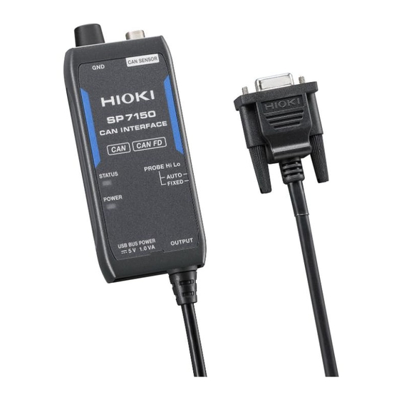
Page 16: Sp7150 Can Interface
Part Names and Functions SP7150 CAN Interface Front Rear Right side Name Function Connect to the CAN signal source ground or to the automobile’s body Ground terminal (ground or body ground connected to the vehicle battery’s negative p. 18 terminal). -
Page 17: Sp9200 Signal Probe
Connector with lock p. 16 the lock is engaged when connecting to the sensor. Place the cable under test into the slit in the guard hook and Guard hook p. 22 clamp it in place with the detection electrode. HIOKI SP7001A961-01... -
Page 18: Led Lighting/Flashing Specifications
Self-test error (failure) Steady red Signal not detected Steady green Signal detected Flashing green Probe high/low reverse connection Flashing red warning SP7100/SP7150 CAN Interface SP7100 SP7150 Product status POWER LED CH1, CH2 LED STATUS LED Self-test error (failure) Flashing green... -
Page 19: Preparing Before Use
“2.6 Supplying Power” (p. 21) “2.5 Connecting the CAN Interface” (p. 20) Connect the SP7100 CAN Interface’s CAN signal output connector to the CAN interface-equipped analyzer, logger, instrument, or other device with which you wish to use it. HIOKI SP7001A961-01... -
Page 20: Connecting The Signal Probes
SP9250 Example: SP9200 Signal Probe SP9200 SP7001/SP7002 Non-Contact CAN Sensor Insert until you hear a clicking sound to lock the connector. SP7001/SP7002 Non-Contact CAN Sensor SP9200 connector with lock SP7001 or SP7002 Signal Probe connector HIOKI SP7001A961-01... -
Page 21: Connecting The Non-Contact Can Sensor
Connecting the Non-Contact CAN Sensor 2.3 Connecting the Non-Contact CAN Sensor Connect the SP7001/SP7002 Non-Contact CAN Sensor’s output connector to the SP7100/SP7150 CAN Interface’s Non-Contact CAN Sensor connector. CAUTION Handle each connector of the product. Do not use tools. Subjecting the connectors to excessive force could damage them. -
Page 22: Connecting The Ground Terminal
Connecting the Ground Terminal 2.4 Connecting the Ground Terminal SP7100/SP7150 CAN Interface ground terminal Connect the CAN Interface to the vehicle’s body ground or other suitable grounding point. Connect the ground connection cable connected to the CAN Interface to the CAN signal source ground or to the vehicle’s body (ground connected to the vehicle battery’s negative terminal or body... - Page 23 Note that there is no AC coupling between the Signal Probe and the sensor ground, as illustrated in the equivalent circuit diagram, and exercise caution to avoid creating a short-circuit. Short-circuit protection provided by AC coupling functions only for DC voltages. HIOKI SP7001A961-01...
-
Page 24: Connecting The Can Interface
The SP7100’s output connector carries both CH1 and CH2 data. Connect the SP7100 or SP7150 after checking the pin assignment in use for the D-sub 9-pin by the SP7100/SP7150 and the device you plan to use. -
Page 25: Supplying Power
You can supply power to the SP7100 CAN Interface with either the L9500 Power Cable or the Z1008 AC Adapter. And you can supply power to the SP7150 CAN Interface with either the L9510 USB Cable or the Z1013 AC Adapter. Choose the power source that is best suited to your operating environment. -
Page 26: Connecting The Signal Probes To The Can Bus
• Position the probe so that the cable under test is in contact with the back of the detection electrode. • Proper detection will be impossible if the cable under test is positioned too shallowly or angled in the guard hook. HIOKI SP7001A961-01... - Page 27 The probe is designed so that while it is locked in place, the grip will be locked so that it cannot be rotated (to prevent inadvertent loosening). Rotate the grip while pulling it towards you. The guard hook will open. Remove the cable under test. HIOKI SP7001A961-01...
-
Page 28: When Using The Sp9250
• Position the probe so that the cable under test is in contact with the back of the detection electrode. • Proper detection will be impossible if the cable under test is positioned too shallowly or angled in the guard hook. Cable under test HIOKI SP7001A961-01... -
Page 29: Inspecting The Product Before Use
2.8 Inspecting the Product Before Use Before using the product, inspect it for any damage that may have occurred during storage or shipment. If you find any damage, contact your authorized Hioki distributor or reseller. Inspect all parts. Is there any cracking or damage Send back the product for repair. - Page 30 Inspecting the Product Before Use HIOKI SP7001A961-01...
-
Page 31: Functionality
Situations where it may be necessary to use high-sensitivity mode • When the differential voltage of the CAN communications signals on the CAN bus is low • When the CAN bus cable has thick insulation • When the CAN bus cable has rigid insulation HIOKI SP7001A961-01... -
Page 32: Probe Setting Function (Automatic Polarity Selection)
Probes are connected to the CAN bus in reverse, it will switch the high and low detected signals via its internal circuitry. This function will operate in approximately 2 seconds as long as the CAN bus load factor is approximately 5% or greater. Probe setting selector HIOKI SP7001A961-01... -
Page 33: Output Bus Error Detection Function
Output Bus Error Detection Function 3.3 Output Bus Error Detection Function This function determines that an output error has occurred when the SP7100 or SP7150 CAN Interface is unable to output a proper CAN signal to the bus connected to the CAN signal output connector. - Page 34 Output Bus Error Detection Function HIOKI SP7001A961-01...
-
Page 35: Specifications
4h along X-axis and 2h along Y- and Z-axes at a vibration acceleration of 45 m/s (4.6 G) Power supply Supplied from SP7100 or SP7150 External dimensions Approx. 44W × 85H × 20D mm (1.73″W × 3.35″H × 0.79″D) (excluding protruding... - Page 36 125 kbit/s to 1 Mbit/s (SP7001, SP7002) communications speeds CAN FD: 125 kbit/s to 3 Mbit/s (SP7001) Total delay time Combined with SP7100 or SP7150 CAN Interface 130 ns (typical) (from detection of CAN signal to output) Differential detection Recessive: 1.5 V (typical) or greater...
- Page 37 Set the Non-Contact CAN Sensor's sensitivity mode with the SENSITIVITY selector. • DEFAULT Normal mode selection function • HIGH High-sensitivity mode LED lighting/flashing STATUS specifications Self-test error Steady red Signal not detected Steady green Signal detected Flashing green Probe high/low reverse connection warning Flashing red HIOKI SP7001A961-01...
-
Page 38: Sp7100 Can Interface
Accessories Refer to p. 3. Options SP7001 Non-Contact CAN Sensor SP7002 Non-Contact CAN Sensor L9500 Power Cable (for connecting an external battery; terminates in wires; approx. 2 m long) SP9900 Split Cable Z1008 AC Adapter C1013 Carrying Case HIOKI SP7001A961-01... - Page 39 TCAN1051GV (SP7100 does not have receiver function and communications arbitration function.) Total delay time In combination with SP7001/SP7002 Non-Contact CAN Sensor 130 ns (typical) (from detection of CAN signal to output) Ω CAN terminal resistance 60 (typical) built in HIOKI SP7001A961-01...
- Page 40 CAN sensor connected Steady (on) Reflects CAN sensor STATUS (according to STATUS) Output bus error Steady (on) Flashes, alternately quickly between the red and green detection function LEDs for the channel on which the output bus error was detected. HIOKI SP7001A961-01...
-
Page 41: Sp7150 Can Interface
SP7150 CAN Interface 4.3 SP7150 CAN Interface 1. General specifications Operating environment Indoors, Pollution Degree 2, altitude up to 2000 m (6562 ft.) Temperature: −40°C to 85°C (−40°F to 185°F) Operating temperature −40°C to 60°C (−40°F to 140°F), 80% RH or less (no condensation) - Page 42 CAN FD: 125 kbit/s to 3 Mbit/s Connect CAN signal output connector directly to target device CAN transceiver TCAN1051GV (SP7150 does not have receiver function and communications arbitration function.) Total delay time In combination with SP7001/SP7002 Non-Contact CAN Sensor 130 ns (typical)
- Page 43 SP7150 CAN Interface 3. Function specifications Probe setting selector Serves as a switch for setting the Non-Contact CAN Sensor’s probe setting function when used in combination with the Non-Contact CAN Sensor. • FIXED Outputs the detected signals without additional processing even if the Non-Contact CAN Sensor detects that the Signal Probe connections to the CAN bus’s CAN_H and...
-
Page 44: Sp9200 Signal Probe
Output connector Special anti-vibration connectors Durability: 100 insert/remove cycles Detection conditions Within operating temperature and humidity range and below temperature at which cables under test become soft Compatible cables AVS/AVSS-compliant cables Compatible cable φ1.2 mm to 2.0 mm diameter HIOKI SP7001A961-01... -
Page 45: Sp9250 Signal Probe
Special anti-vibration connectors Durability: 100 insert/remove cycles Detection conditions Within operating temperature and humidity range and below temperature at which cables under test become soft Compatible cables AVS/AVSS-compliant cables Compatible cable φ1.2 mm to 2.0 mm diameter Durability 10,000 times HIOKI SP7001A961-01... -
Page 46: Sp9900 Split Cable (Dedicated Option For Sp7100)
CH1 CAN Low CH2 CAN Low CH1 GND CH1 GND CH2 GND N.C. N.C. N.C. Shield Shield Shield CH2 GND N.C. N.C. CH1 CAN High CH1 CAN High CH2 CAN High CH2 CAN High N.C. N.C. N.C. N.C. N.C. HIOKI SP7001A961-01... -
Page 47: Maintenance And Service
Do not leave the C1013 Carrying Case in locations where it would be subject to direct sunlight or high temperatures, for example inside a vehicle. High temperatures may deform the shape of the inside of the case. Stow the product in the C1013 Carrying Case with connectors connected. HIOKI SP7001A961-01... - Page 48 Signal Probes’ guard hooks or detection electrodes may adversely affect signal detection. Fibers and other material that get into the Signal Probes’ moving parts could cause them to malfunction. If the product becomes dirty, moisten a soft cloth with water or neutral detergent and gently wipe it clean. HIOKI SP7001A961-01...
-
Page 49: Troubleshooting
Troubleshooting 5.1 Troubleshooting If damage is suspected, contact your authorized Hioki distributor or reseller after reviewing the contents below. CAN signal detection is unstable. Check/consider Solutions • Verify that the cable (CAN bus) under test has been properly inserted between the detection electrode and guard hook. -
Page 50: You Are Unable To Detect Can Signals Stably When Using The Product In An Environment Where It Is Exposed To Vibrations, For Example In Road Testing
(CAN bus) under test? • Fix the Signal Probes and cable (CAN bus) under p. 22 test in place so that they do not vibrate. p. 24 • Are the Signal Probes or the cable (CAN bus) under test unstable? HIOKI SP7001A961-01... - Page 51 HIOKI SP7001A961-01...
- Page 52 HIOKI SP7001A961-01...
Need help?
Do you have a question about the SP7150 and is the answer not in the manual?
Questions and answers