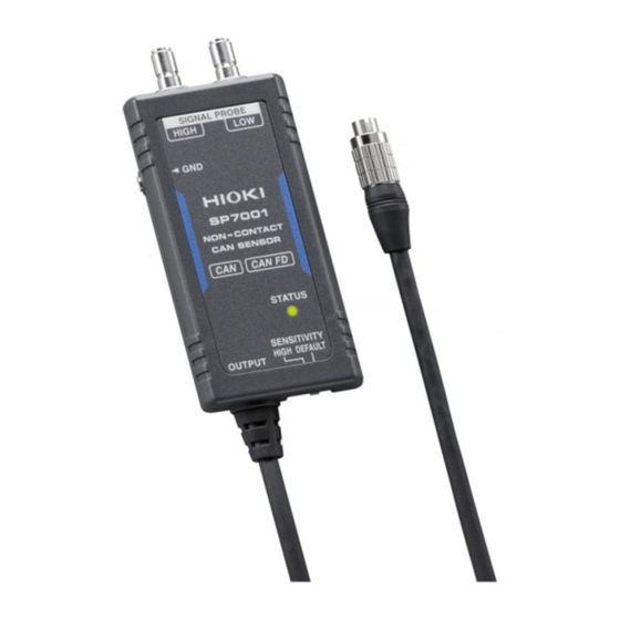
Hioki SP7001 User Manual
Causes of “output bus error detection”
Hide thumbs
Also See for SP7001:
- Instruction manual (44 pages) ,
- Instruction manual (52 pages) ,
- Instruction manual (52 pages)
Advertisement
The SP7001/SP7002: Causes of "Output Bus Error Detection"
LED Warning when the Detected CAN Bus Signal Differs from the Sensor's Output Signals
Points
・The SP7000 series non-contact CAN sensor reliably outputs the acquired CAN signal without delay.
・If any signal is output from the device to which this product is connected, the output waveform will change due to
the collision between the acquired CAN signal and the signal from the device. At this time, the LEDs corresponding
to each channel are alternately lit in
LED lights in normal condition (flashing green)
Detected signal
Signals are the same
LED lights with "output bus error detection" function (red and green alternately flash)
Output signal of the Non-Contac CAN Sensor→ ← Input signal from the connected device
The original shape of the CAN signal can break down and trigger the "output bus error detection " function for
various reasons. The following are the most common cases.
■ CASE 1: The connected device outputs a CAN signal
The connected device may be outputting a CAN signal such as an output command to an ECU gateway. Please set
the connected devise to a read-only mode or make sure in another way that it does not output a CAN signal.
■ CASE 2: The pin assignment of the connected device differs from that of the sensor
Please use the sensor after checking that the pin assignment of the connected device is the same as the Non-
Contact CAN Sensor. Especially in cases where the CAN High or CAN Low is connected to the GND or Vcc of the
connected device, a signal cannot be output.
red
and
green
by the "output bus error detection" function.
=
Output signal
LED
LED
© 2020 HIOKI E.E. CORPORATION
Connected device
Signal collision abnormality
Connected device
Signal detected
Flashing green
Output bus error
Red/green
are alternately lit
detection
※Continues to the back
A_UG_SP0002E01
Advertisement
Table of Contents

Summary of Contents for Hioki SP7001
- Page 1 The SP7001/SP7002: Causes of “Output Bus Error Detection” LED Warning when the Detected CAN Bus Signal Differs from the Sensor’s Output Signals Points ・The SP7000 series non-contact CAN sensor reliably outputs the acquired CAN signal without delay. ・If any signal is output from the device to which this product is connected, the output waveform will change due to the collision between the acquired CAN signal and the signal from the device.
- Page 2 LED to return to indicating regular operation (flashing green). This document is accurate as of April of 2020. Content such as specifications may be revised or altered without notice. © 2020 HIOKI E.E. CORPORATION A_UG_SP0002E01...


Need help?
Do you have a question about the SP7001 and is the answer not in the manual?
Questions and answers