Sign In
Upload
Download
Table of Contents
Contents
Add to my manuals
Delete from my manuals
Share
URL of this page:
HTML Link:
Bookmark this page
Add
Manual will be automatically added to "My Manuals"
Print this page
×
Bookmark added
×
Added to my manuals
Manuals
Brands
Hioki Manuals
Accessories
CT9555
Instruction manual
Hioki CT9555 Instruction Manual
Sensor unit
Hide thumbs
1
2
3
4
5
6
7
8
9
10
11
12
13
14
15
16
17
18
19
20
21
22
23
24
25
26
27
28
29
30
31
32
33
34
35
36
37
38
39
40
41
42
43
44
45
46
47
48
49
50
51
52
53
54
55
56
57
58
59
60
61
62
63
64
65
66
67
68
69
70
71
72
73
74
75
76
77
78
79
80
81
82
83
84
85
86
87
88
89
90
91
92
93
94
95
96
97
98
99
100
101
102
103
104
105
106
107
108
109
110
111
112
113
114
115
116
117
118
page
of
118
Go
/
118
Contents
Table of Contents
Bookmarks
Table of Contents
English
Table of Contents
Introduction
Confirming Package Contents
Safety Information
Operating Precautions
Overview and Features
X84; Overview
X84; Features
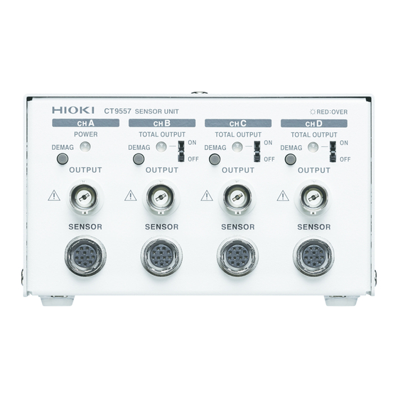
Parts Names and Functions
Pre-Operation Inspection
X84; Use CT9555 or CT9556
Measurement Methods
X84; Use CT9557
X84; When Using the Addition Function
X84; Connection/Disconnection Method of Sensors
X84; Connect the BNC Cable
X84; Connect CT9557 and the Measuring Device with the CT9904
X84; Remove CT9557 and the Measuring Device
Application Examples
X84; Monitor the Current (CT9555, and CT9556)
Function)
X84; Measuring Leakage Current or Current in a Non- Measurable Line (Addition Function)
X84; CT9555 (1-Channel), and CT9556 (1-Channel/Rms) Specifications
Specifications
X84; CT9557 (4-Channel/Rms) Specifications
Maintenance and Service
汉语
装箱内容确认
关于安全
使用注意事项
概要和特点
各部分的名称与功能
测量前的检查
使用 Ct9555 或 Ct9556
测量方法
使用 Ct9557
使用加法功能时
传感器的连接 / 拆卸方法
利用 Ct9904 连接 Ct9557 与测量仪器
连接 Bnc 电缆
拆下 Ct9557 与测量仪器
应用示例
观测电流 (Ct9555 、 Ct9556)
测量大电流、多个电路 (加法功能
测量泄漏电流、非测量线路的电流 (加法功能
Ct9555 ( 1 通道) 、 Ct9556 ( 1 通道 /Rms ) 规格
Ct9557 ( 4 通道 /Rms ) 规格
维护和服务
Advertisement
Quick Links
Download this manual
CT9555
CT9556
CT9557
センサユニット
SENSOR UNIT
传感器单元
Oct. 2018 Revised edition 2
CT9555A960-02 18-10H
取扱説明書
Instruction Manual
使用说明书
JA/EN/CN
Table of
Contents
Previous
Page
Next
Page
1
2
3
4
5
Advertisement
Chapters
English
41
汉语
81
Table of Contents
Need help?
Do you have a question about the CT9555 and is the answer not in the manual?
Ask a question
Questions and answers
Related Manuals for Hioki CT9555
Accessories Hioki CT7631 Instruction Manual
Ac/dc current sensor (4 pages)
Accessories Hioki CT9556 Instruction Manual
Sensor unit (118 pages)
Accessories Hioki CT9557 Instruction Manual
Sensor unit (118 pages)
Accessories Hioki SP7150 Instruction Manual
Non-contact can sensor, can interface, signal probe (52 pages)
Hioki 9555-10 - Sensor Manual
(article)
Accessories Hioki 9298 Instruction Manual
Clamp on sensor (2 pages)
Accessories Hioki Z2018 Instruction Manual
Heat flow sensor (2 pages)
Hioki 9667 - Flexible Clamp On Sensor Manual
(article)
Hioki 9743-10 - Optical Sensor Manual
(article)
Accessories Hioki SP7001 User Manual
Causes of “output bus error detection” (2 pages)
Accessories Hioki 9675 Instruction Manual
Clamp on leak sensor (2 pages)
Accessories Hioki Z2012 Instruction Manual
Heat flow sensor (2 pages)
Accessories Hioki 9694 Instruction Manual
Clamp on sensor (2 pages)
Accessories Hioki 9279 Instruction Manual
Universal clamp on ct (54 pages)
Accessories Hioki SP7002 Instruction Manual
Non-contact sensor, can interface, signal probe (52 pages)
This manual is also suitable for:
Ct9556
Ct9557
Table of Contents
Print
Rename the bookmark
Delete bookmark?
Delete from my manuals?
Login
Sign In
OR
Sign in with Facebook
Sign in with Google
Upload manual
Upload from disk
Upload from URL


Need help?
Do you have a question about the CT9555 and is the answer not in the manual?
Questions and answers