Table of Contents
Advertisement
Quick Links
Advertisement
Table of Contents

Related Manuals for Mirion Technologies RDS-31iTxSD


Summary of Contents for Mirion Technologies RDS-31iTxSD
- Page 1 RDS-31iTxSD Multi-purpose Survey Meter User Manual Doc. No. 2096 6343 Ver. 1.03 ...
- Page 2 There is a feedback form at the end of this document. ATTENTION! The RDS-31iTxSD Multi-purpose Survey Meter does not contain any hazardous or dangerous substances and can be recycled accordingly. The batteries of the device must be recycled separately as instructed by the manufacturer of the batteries.
-
Page 3: Table Of Contents
Table of Contents Introduction ................1 RDS-31iTXSD S/R Multi-Purpose Survey Meter ......... 1 Taking the Instrument into Use for the First Time ....2 Inserting Batteries ................ 2 Switch On ..................4 ... - Page 4 WRM transmission ..............39 6.10 Indication Unit ................39 Maintenance and Decontamination ......... 39 RDS-31iTxSD Specifications ........... 41 Radiological Characteristics ............41 Functional Characteristics ............41 Electrical Characteristics .............. 42 ...
-
Page 5: Introduction
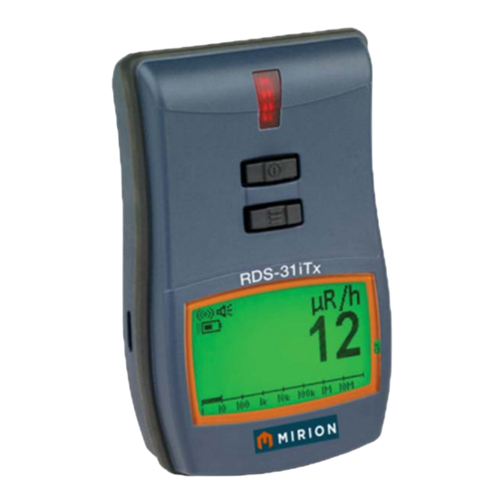
1. Introduction 1.1 RDS-31iTXSD S/R Multi-Purpose Survey Meter The RDS-31iTxSD Multi-purpose Survey Meter continues the line of the MIRION survey meters offering modern design and approach to a wide range of radiation monitoring applications. RDS-31iTxSD is a small handheld, battery-operated survey instrument utilizing an energy compensated single large PIN diode as a primary detector. -
Page 6: Taking The Instrument Into Use For The First Time
This allows the alarm to be triggered in case a too high dose rate or an accumulated dose is measured. The RDS-31iTXSD is ready for use after the batteries (2 x IEC LR6/AA) have been installed. 2 Taking the Instrument into Use for the First Time 2.1 Inserting Batteries... - Page 7 The instrument uses two IEC (LR6/ HR6) AA-size batteries. The use of alkaline batteries is recommended, but rechargeable NiMH batteries can also be used. The polarity of the batteries can be seen in the picture below. It is also engraved in the bottom of the battery compartment. Insert the batteries and secure the battery cap.
-
Page 8: Switch On
Main Parts of the RDS-31iTxSD This paragraph presents the main parts of the instrument. 3.1 Display of the RDS-31 The display of the RDS-31 is a 128 x 64 pixel graphical display with the Energy Saving Backlight (ESB). - Page 9 Display symbols and related functions: Symbol Function Symbol Function Button and alarm buzzer Button and alarm buzzer enabled enabled. Button buzzer disabled, Audible chirp enabled. alarm buzzer enabled Audible chirp disabled. Button buzzer enabled, Note: If Speaker and Chirp alarm buzzer disabled symbol are not visible device is muted The Vibration Alarm Alarm Condition exists Activated Waiting for external External detector is detector detection. connected Beta detector Alpha Detector RF‐link active Blinking`life’ indicator on ...
-
Page 10: Connectors And Strap
3.2 Connectors and Strap The connector for an external detector and an external charger is in the bottom of the instrument. There is also the fixing lug of the wrist strap. The round connector (Binder 702 series) is used for external probes, for cable connections and for external alarming devices. -
Page 11: Using The Buttons And Special Features
to prevent any unwanted activation of the button e.g. while wearing gloves. The two buttons have been named On/Off [ ] and Menu [Ξ]. This indicates the main purpose of the buttons. The On/Off button switches (through the menu selection) the instrument on and off. -
Page 12: Normal Usage Of The Buttons
on for 24 seconds and the Menu button would give the current accumulated dose in the display for 14 seconds. In the background, the instrument would perform the diagnostics and record the current status, dose and dose rate into the histogram memory with each pushing of the button (Manual histog. -
Page 13: Operation
5 Operation Switch On Press the [ ] button until all the display pixels are turned on and an audible signal is heard. The meter performs a self-test function: All the display pixels are turned on The buzzer is activated ... -
Page 14: Indication Of The Measuring Unit
The instrument starts measuring the dose rate and accumulating the dose immediately when the instrument is switched on. During the initial start-up, the instrument informs the user that the time of the Real Time Clock has not been set (flashing ‘TIME NOT SET’... -
Page 15: Operating The Instrument Menu
5.3 Operating the Instrument Menu The actual Menu list is completely dependent on the existing instrument configuration. This means that in the most basic form there are no items in the menu list that can be activated with the button operations. Pressing the button will only illuminate the display and perform some internal functions. -
Page 16: Show And Reset Cumulative Dose (Dose)
5.4.1 Show and Reset Cumulative Dose (DOSE) The instrument integrates the cumulative dose continuously into a dose register when switched on. To see the cumulative dose: Activate the menu (Short [Ξ]) and scroll (Short [Ξ]’s) until display changes to DOSE. ... -
Page 17: Chirp Off And Setting Divisor (Chirp)
The maximum dose rate is now set to zero. The display shows the 0.0 µSv/h (0 µrem/h) without blinking and if no button actions take place within the time-out period, the display returns to the dose rate. 5.4.3 Chirp Off and Setting Divisor (CHIRP) The chirp function can be used to activate or... -
Page 18: Show And Change Dose Rate Alarm Level (Fx.ral/Sq.ral)
To change the chirp state: While the current chirp state is displayed, press [ ]shortly and the display shows the state of the related Chirp function blinking Scroll with short [Ξ] until the desired value (CA:OFF| CA:ON; CV:OFF| CV:ON; CH:/1|…CH:/50) is given ... -
Page 19: Fixed Dose Rate Alarm Level
NOTE: The mode can be selected only by using the CSW-31 software. 5.4.4.1 Fixed Dose Rate Alarm Level: There are 8 different levels for dose rate alarm: disabled, 10, 50, 100, 500, 1 000, 5 000, 10 000 or 50 000 µSv/h or mrem/h. The user may select any one of these to be the active alarm threshold level. -
Page 20: Sequential Dose Rate Alarm
5.4.4.2 Sequential Dose Rate Alarm: When sequential dose rate alarm function is enabled, all the eight dose rate alarm levels will be active in the order of the list (the default values are the same as in the “fixed dose rate alarm level”). -
Page 21: Show And Change Dose Alarm Level (Fx.dal/Sq.dal)
SQ.RAL SUB‐menu . . . ↓ ↑ 50.00 mSv/h ↓ ↑ OFF *) ↓ ↑ 10.00 µSv/h Choose SQ.RAL → *) Option ↓ ↑ 50.00 µSv/h ↓ ↑ 100.0 µSv/h ↓ ↑ 500.0 µSv/h 1.000 mSv/h 5.000 mSv/h 10.00 mSv/h ... - Page 22 To see the current dose alarm threshold level: Activate the menu (Short [Ξ]) and scroll (Short [Ξ]’s) until display changes to FX.DAL The current dose alarm threshold value is displayed on right side of the display. To change the current dose alarm level: ...
-
Page 23: Sequential Dose Alarm
5.4.5.2 Sequential Dose Alarm: NOTE: the sequential dose alarm function can be taken into use with the CSW-31 Software only! When the sequential dose alarm function is enabled, all the eight dose alarm levels will be activated in the order of the magnitude (the default values are the same as in the Fixed dose alarm). -
Page 24: Time To Dose Alarm (Tm.2.Al)
SQ.DAL SUB‐menu . . . ↓ ↑ 500.0 mSv ↓ ↑ OFF *) ↓ ↑ Choose SQ.DAL → 100.0 µSv *) Option ↓ ↑ 500.0 µSv ↓ ↑ 1.000 mSv ↓ ↑ 5.000 mSv 10.00 mSv 50.00 mSv 100.0 mSv *) Only OFF or lowest value on the ... -
Page 25: Diagnostics (Diag)
To check the status of the Time to Dose Alarm: Activate the menu (Short [Ξ]) and scroll (Short [Ξ]’s) until display changes to TM.2.AL The current status is displayed (the remaining time to reach the current dose alarm level in form of xxh xxm or disabled = DISAB). - Page 26 To activate the diagnostics functions: Activate the menu (Short [Ξ]) and scroll (Short [Ξ]’s) until display changes to DIAG Press [ ]shortly The display shows blinking “8.8.8.8.8” DIAG SUB‐menu . . . ↓ ↑ Information Field B: 65% Last measured battery capacity ...
-
Page 27: Communication (Conn)
The display provides the CAL.CHECK o While the CAL.CHECK is displayed o Press intermediate [ ] o The check dose rate value is set to 1 mSv/h as a default. With the CSW-31 Pro, the value can be set to a more optimal value between 300 µSv/h …... - Page 28 adapter is activated and remains waiting the RDS-31 instrument to be connected to the adapter. When the Cable-adapter to the PC–link is established and the instrument is connected to the adapter, the communication between instrument CSW-31 activated automatically. When the RF-adapter to PC–link is established, the instrument is manually set to start the communication.
-
Page 29: Histogram (Histo)
5.4.9 Histogram (HISTO) The Histogram functions of the RDS-31 are very versatile. The menu functions of the Histogram are summarized in the following table. First HISTO level Second STATE L: (location) I: (interval) Manual Clear level Third Show the Show the Show the Picks Clears the... - Page 30 The histogram function of the user interface has the following main features: STATE: The STATE provides the currently active status of the timed histogram logging. When ON the measurement data is stored into the histogram memory using the determined interval.
- Page 31 Location Submenu . . . Numbered Location 254 ↓ ↑ Numbered Location 255 ↓ ↑ Choose LOC: 0 → Option ↓ ↑ User modified Mnemonic ROOM1 ↓ ↑ User modified Mnemonic ROOM2 ↓ ↑ User modified Mnemonic ROOM3 Default Location LOC.4 Mnemonic ...
- Page 32 Manual: It is also possible to store manual samples into the histogram memory. In this case, only the immediate value in the display is stored. With timed logging, the average and maximum dose rate values are also stored. Clear: ...
-
Page 33: Other Histogram Records
The duration to receive independent results 1000 Time Indep. Res/h 0,01 Dose Rate [µSv/h] Typical result for the RDS-31 standard GM-detector and counting statistics, not to be used as a specification. 5.4.9.1 Other Histogram Records In addition to the preprogrammed and manual histogram data storing, there are automatic records that are stored into histogram memory: ... -
Page 34: Wrm Communication (Wrm)
These special memory areas cannot be cleared with the CSW-31 LITE/PRO software but require special service. 5.4.10 WRM Communication (WRM) The RDS-31iTxSD uses an internal radio modem enabling the dose/dose rate data transmission to any WRM compatible system. The WRM communication time interval can be set in the range of 2 to 60 seconds. - Page 35 there are additional features, listed in the 4 table below, that can be configured into the instrument Shortcuts. With CSW-31 LITE there can be one Shortcut to the menu button ([Ξ]) only. With the CSW-31 PRO, the user can configure two shortcuts to both buttons ([ ] and [Ξ]) allowing up to 4 different choices.
- Page 36 CSW-31 LITE Shortcut Function Operation Shortcut-4 Chirp set When (Long press of activating the shortcut, the Ξ display of the instrument goes into the menu item CHIRP. The normal button operations are allowed from this point onwards. Maximum dose When rate activating the shortcut, the...
- Page 37 CSW-31 PRO Shortcuts Shortcut Function Time Shortcut-1 An intermediate Pressing more press of [ ] than 0.75s, but less than 1.5s A Long press of [ ] Shortcut-2 Pressing more than 1.5s Shortcut-3 An intermediate Pressing more press of [ than 0.75s, but Ξ...
-
Page 38: Other Displayed Messages
Connection The menu item of CONN, indicating communication states. The normal button operation is allowed. Histogram The menu item of HISTO, indicating histogram function state. The normal button operation is allowed. Chg. hist. The submenu of HISTO, allowing state configuration of histogram functions. Manual histog Takes manual histogram sample. -
Page 39: Error (Def/Err)
The overflow alarm cannot be reset. Note: When the dose rate overflow has been activated, there will be a message from this event in the dose read-out. When the dose is given, the display alternates between “DR.OFL” <-> dose. This flag will be set when the dose is reset. -
Page 40: Show And Reset Cumulative Dose (Dose)
Pressing any button or length will activate the backlight. To only achieve the backlight activation, press the [ ]-button shortly. Option Effect Configuration When the push button is pressed, the display backlight is lit for 24 seconds (timeout mode). Configuration The backlight is on permanently (constantly on –mode). -
Page 41: Show And Change Dose Rate Alarm Level (Fx.ral/Sq.ral)
Configuration 6: The pulse rate from the detector is divided by a value from the fixed list: 1/1, 1/2, 1/5, 1/10, 1/20 and 1/50 The state X is either Enable or Disable 6.4 Show and Change Dose Rate Alarm Level (FX.RAL/SQ.RAL) The Dose rate alarm is always measured from the internal tube even when an external detector has been inserted. -
Page 42: Battery And Display Test (Diag)
6.7 Battery and Display Test (DIAG) The diagnostics function is performed every 10 minutes while the instrument is set ON. The diagnostics results are stored into the histogram memory: When the instrument is switched ON In case of an error in the diagnostics ... -
Page 43: Wrm Transmission
WRM transmission The RDS-31iTxSD model has an extra radio modem which can be used for transmitting the dose/dose rate data to a master system at selected time intervals. Option Effect Configuration 1: Disabled Configuration 2: Enabled 6.10 Indication Unit The displayed units can be chosen between Sv and rem. - Page 44 Note After fitting fresh batteries, it is recommended to perform the functional test (DIAG). If the flashing low battery symbol appears in the display after the test, refit the batteries. Note: When changing the battery type between alkaline and rechargeable, use the CSW-31 software to indicate the change to the instrument.
-
Page 45: Rds-31Itxsd Specifications
8 RDS-31iTxSD Specifications Order catalog # 1233-285: RDS-31iTxSD; Sv units; Survey Meter WRM 2,4GHz including WRM-radio module for European radio frequency Order catalog # 1233-283: RDS-31iTxSD; rem units; Survey Meter WRM 900MHz including WRM-radio module for US radio frequency 8.1 Radiological Characteristics... -
Page 46: Electrical Characteristics
Histogram data stored in XML format; allowing additional histogram analyzing capabilities when downloaded from CSW-31 software to a spreadsheet. Real Time Clock (RTC) function. Configurable audible, visual and vibration alarm. RF-communication and USB-communication with suitable adapter. ... -
Page 47: Environmental Characteristics
8.5 Environmental Characteristics Operating temperature -25 °C...+60 °C (-13 °F to 131 °F) Storage temperature -40 °C...+70 °C (-40 °F to 158 °F) Relative humidity: up to 85% at +35 °C (95 °F) Fulfills the RF-immunity levels of applicable standards 8.6 Connector ... -
Page 48: Accessories
9 Accessories USB-RF Link-31 LITE + CSW-31 Configuration Software Order number: 1233-262 USB-RF Link-31 PRO + CSW-31 Configuration Software Order number: 1233-263 USB-Cable Link-31 LITE + CSW-31 Configuration Software Order number: 1233-264 USB-Cable Link-31 PRO + CSW-31 Configuration Software Order number: 1233-265 The Configuration Software (CSW-31) is used to check the status of the instrument, to change its operational parameters... - Page 49 Range: 0 to 10 000 cps GMP-12SD Gamma probe for RDS-31 Order Number: 1233-286 Range: 100 µSv/h to 10 Sv/h GMP-12UW Gamma probe for RDS-31 Order Number: 1233-287 Range: 0 to 10 000 cps ABP-150 Alpha/Beta probe for RDS-31 Order Number: 1233-289 Range: 0 to 100 000 cps GMP-12GSD Gamma probe for RDS-31...
-
Page 50: Feedback Form
FEEDBACK FORM We are continuously working hard at producing correct and easy‐to‐read technical documents. However, complex systems are often difficult to explain or understand and therefore mistakes or inadequacies may occur occasionally in the documentation process. To correct these errors we would like to hear your opinion on this document. If you have noted mistakes, or if there are parts that are unclear, please let us know. Make a copy of this page, describe the problem and send the copy to us here in RADOS. To: Mirion Technologies (RADOS) Oy/ Technical Documents P.O. Box 506, FIN‐20101 Turku, Finland Fax: +358‐2‐468 4601 E‐mail: info‐fi@mirion.com This way you will help us in supplying you with even better documents. The best feedback will be rewarded. Notes on this document Name of the document: ‐‐‐‐‐‐‐‐‐‐‐‐‐‐‐‐‐‐‐‐‐‐‐‐‐‐‐‐‐‐‐‐‐‐‐‐‐‐‐‐‐‐‐‐‐‐‐‐‐‐ Issue date: ‐‐‐‐‐‐‐‐‐‐‐‐‐‐‐‐‐‐‐‐‐‐‐‐‐‐‐‐‐‐‐‐‐‐ ‐‐‐‐‐‐‐‐‐‐‐‐‐‐‐‐‐‐‐‐‐‐‐‐‐‐‐‐‐‐‐‐‐‐‐‐‐‐‐‐‐‐‐‐‐‐‐‐‐‐‐‐‐‐‐‐‐‐‐‐‐‐‐‐‐‐‐‐‐‐‐‐‐‐‐‐‐‐‐‐‐‐‐‐‐‐‐‐‐ Description of the mistake or problem: Correction: ... - Page 51 47 ...
Need help?
Do you have a question about the RDS-31iTxSD and is the answer not in the manual?
Questions and answers