Advertisement
IN770PAN00*O000
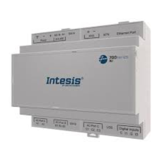
Panasonic VRF gateway with
KNX, Serial and IP support
Order Code: IN770PAN00*O000
* Stands for the Intesis gateway capacity and varies depending on the specific gateway acquired
Installation Sheet rev.1.0
HMS Industrial Networks S.L.U ©
SAFETY INSTRUCTIONS
WARNING
!
Follow these safety and installation instructions carefully.
Improper work might lead to serious harm to your health
and damage this Intesis gateway and/or any other
equipment connected to it.
Only accredited technical personnel, following all the safety instructions
and in accordance with the country's legislation for electric equipment
installation, can install and manipulate the gateway.
Install the gateway indoors, in a restricted access location, and
sheltered from direct solar radiation, water, high relative humidity, or
dust.
Mount the gateway, preferably, on a DIN rail inside a grounded metal
cabinet following the instructions below.
In the case of wall mount, firmly fix the gateway on a not vibrating
surface following the instructions below.
Disconnect any wires from its power source before manipulating and
connecting them to the Intesis gateway.
Use a SELV-rated NEC Class 2 or Limited Power Source (LPS) power
supply.
Respect the expected polarity of power and communication cables
when wiring the gateway.
Supply the correct voltage to power the Intesis gateway. See the
voltage range admitted by the gateway in the technical specifications
table at the end of this document.
CAUTION: Connect the gateway only to networks without routing to the
outside plant. All communication ports are considered for indoor use
and can be connected to SELV circuits only.
This gateway was designed for installation inside an enclosure. When
working inside an enclosure (ex. to make adjustments, set switches,
etc.), observe the common anti-static precautions before manipulating
the gateway.
Take precautions when installing it outside an enclosure, in
environments with static levels above 4 kV, to avoid electrostatic
discharges.
Safety instructions in other languages can be found at:
https://intesis.com/docs/manuals/v6-safety
CONFIGURATION
Use the Configuration tool to configure the gateway.
See the instructions to download and install the latest version at:
https://www.intesis.com/products/intesis-maps
Use the Ethernet connection or the Console Port for communication
between the gateway and the Configuration tool (see the Connections
section below). For more info, refer to the
Rev.1.0
© HMS Industrial Networks S.L.U - All rights reserved
This information is subject to change without notice
User
manual.
Owner's Record
The serial number is located at the rear of the gateway.
Record this information in the space provided below.
Refer to it whenever you contact upon your gateway
dealer or support team regarding this product.
Serial No.
INSTALLATION
Follow these instructions to properly install the gateway.
CAUTION: Do not install the gateway in air-handling units or conducts.
Disconnect all installation equipment from the power source before
wiring the Intesis gateway. Make sure there's no current in any bus,
communication cable, and electric wire of the installation.
Follow the instructions below to mount the gateway (wall and DIN rail
mounting are allowed).
Connect a SELV-rated NEC Class 2 or Limited Power Source (LPS)
power supply to the Intesis gateway. Connect the gateway's ground
terminal to the installation grounding. Apply the voltage within the
admitted range and of enough power (see the Technical Specifications
table at the end of this document).
Use a circuit breaker before the power supply. Rating: 250 V,6 A.
Connect the communication cables to the Intesis gateway (see the
Connections section below).
Power the gateway and the installation equipment.
Wall Mount
1. Press the top side mobile clips in the rear panel until you hear
a click.
2. Use the clip holes to fix the gateway on the wall using screws.
(Use M3 screws, 25 mm (1") length).
3. Make sure the gateway is firmly fixed.
Clips in their original position
(for DIN rail mount)
DIN Rail Mount
Keep the clips down in their original position.
1. Fit the gateway's top side clips in the upper edge of the DIN
rail.
2. Use a screwdriver or similar to pull the bottom clip down.
3. Fit the low side of the gateway in the DIN rail and let the clip
switch back to its original position, locking the gateway to the
rail.
4. Make sure the gateway is firmly fixed.
Clips in position for wall mount
URL
https://www.intesis.com
1 / 2
Advertisement
Table of Contents

Subscribe to Our Youtube Channel
Related Manuals for HMS Networks Intesis IN770PAN00 O000 Series


Summary of Contents for HMS Networks Intesis IN770PAN00 O000 Series
- Page 1 Owner’s Record IN770PAN00*O000 The serial number is located at the rear of the gateway. Panasonic VRF gateway with Record this information in the space provided below. KNX, Serial and IP support Refer to it whenever you contact upon your gateway dealer or support team regarding this product.
- Page 2 CONNECTIONS Power Supply Use a SELV-rated NEC class 2 or Limited Power Source (LPS) power supply. If using DC power supply: Respect the polarity labeled on the power connector (+) and (-). Be sure the voltage applied is within the range admitted (12 to 36 VDC +/-10%).
Need help?
Do you have a question about the Intesis IN770PAN00 O000 Series and is the answer not in the manual?
Questions and answers