Advertisement
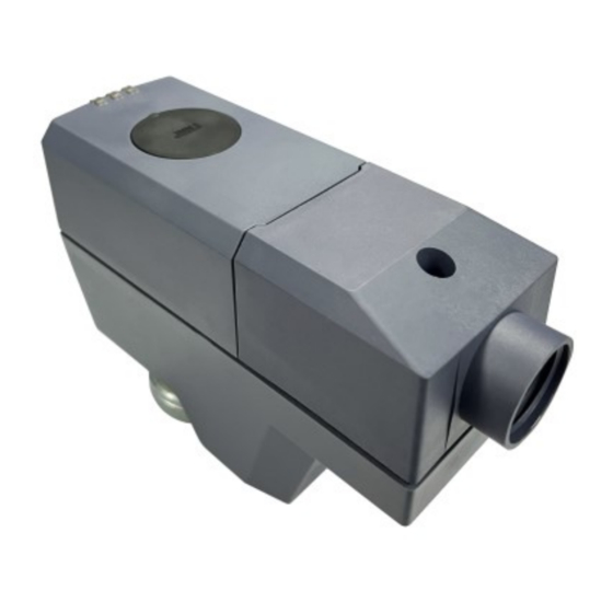
Electromotoric actuator
SSD161S.05DU, SSD161S.25DU, SSD131.29U
A6V12681520_enUS_a
02/09/2023
For Powermite MT Series 2-way and 3-way globe valves
●
SSD161S.05DU (fail-in-place), and SSD161S.25DU (fail-safe): Operating voltage
AC/DC 24 V, modulating control signal DC 0...10 V
●
SSD131.29U (fail-safe): Operating voltage AC 24 V, 3-position (floating) control
signal
●
All actuators are self-calibrating to the valve stroke
●
Modulating variants have position feedback signal
●
Modulating variants are DIP switch configurable for equal percentage/linear flow
characteristic, direct/reverse acting, and the fail-safe variant for fail up/fail down
●
3-position (floating) fail-safe variant is DIP switch configurable for fail up/fail down
●
Direct mounting with coupling nut, no tools required
●
Manual override
●
Position and actuator motion indication (LED)
●
Positioning force 67 lbf (300 N)
●
Parallel operation of multiple actuators possible
Smart Infrastructure
Advertisement
Table of Contents

Related Manuals for Siemens SSD161S.05DU


Summary of Contents for Siemens SSD161S.05DU
- Page 1 SSD161S.05DU, SSD161S.25DU, SSD131.29U For Powermite MT Series 2-way and 3-way globe valves ● SSD161S.05DU (fail-in-place), and SSD161S.25DU (fail-safe): Operating voltage AC/DC 24 V, modulating control signal DC 0...10 V ● SSD131.29U (fail-safe): Operating voltage AC 24 V, 3-position (floating) control signal ●...
-
Page 2: Technical Design
Typical application in chilled ceiling, VAV, unit ventilators, fan coil unit and other terminal unit applications ● Max.10 units of SSD161S.05DU, SSD161S.25DU can operate in parallel, provided the controller output suffices. ● For 3-position actuator, SSD131.29U, 24 actuators can run in parallel. -
Page 3: Led Indication
DC 0...10 V control signal (for SSD161S.25DU, SSD161S.05DU) ● The valve opens / closes in proportion to the con- trol signal at Y. The SSD161… actuators can be set to either a linear or equal percentage control signal response, depending on the position of the associated flow characteristic DIP switch. -
Page 4: Type Summary
Valves and actuators can be ordered assembled in the factory or ordered separately. For easier valve assembly, actuators ordered separately have the actuator stem fully retracted. Equipment combinations Valves Combinable valves for SSD161S.05DU, SSD161S.25DU and SSD131.29U - 2-way PICV Series – 0.5 inch Nominal Line Size Normally Closed (for... -
Page 5: Product Documentation
Combinable valves for SSD161S.05DU, SSD161S.25DU and SSD131.29U - 2-way PICV Series – 1 inch Nominal Line Size Normally Closed (for For Normally Open or replacement only of Normally Closed Inch SSD61_U actuators) applications 599-04304-XX 599-04323-XX Combinable valves for SSD161S.05DU, SSD161S.25DU and SSD131.29U - 2-way PICV Series –... -
Page 6: Self-Calibration
Actuator stem retracts Normally open valve opens, normally closed valve closes NOTICE The actuator must be commissioned only with a correctly mounted valve in place! Self-calibration When operating voltage is applied, the actuators self-calibrate (fully retracted ➙ fully extended ➙ setpoint). Siemens A6V12681520_enUS_a Smart Infrastructure 02/09/2023... -
Page 7: Manual Operation
3. Adjust the position of the actuator stem by rotating Allen wrench (b) illustrated below clockwise or counter-clockwise. – The actuator stem moves down if you rotate clockwise; it moves up if you rotate counter-clockwise. The manually set position is retained. Siemens A6V12681520_enUS_a Smart Infrastructure 02/09/2023... - Page 8 If operating voltage is applied to actuator, press button (a) before and after manually adjusting the position of the actuator stem. If no operating voltage and control signal are applied, manual operation can be done without pressing button (a). Siemens A6V12681520_enUS_a Smart Infrastructure...
- Page 9 Cabling operation 1. Unscrew cover screw 2. Remove cover 3. Remove terminal block and connect or disconnect wire terminals 4. Re-install the terminal block 5. Install the cover 6. Screw in the cover screw Siemens A6V12681520_enUS_a Smart Infrastructure 02/09/2023...
- Page 10 DIP switch configurations DIP Switches Product types SSD161S.25DU SSD161S.05DU SSD131.29U Running direction Direct Stem extends as voltage increases Reverse Stem retracts as voltage increases Stroke characteristic Stroke control provides equal percentage flow characteristic Stroke control provides linear flow characteristic Fail direction...
-
Page 11: Warranty
Comply with all local and currently applicable laws and regulations. Warranty Technical data on specific applications are valid only together with Siemens products listed under "Equipment combinations". Siemens rejects any and all warranties in the event that third-party products are used. -
Page 12: Technical Data
See "Technical design [▶ 2]” Running speed (time for 5.5 mm) SSD161S.05DU, SSD161S.25DU: 5 s/mm ± 25 % (27.5 s ± 25 %) SSD131.29U: 16 s/mm ± 25 % (88 s ± 25 %) Positioning force 67 lbf (300 N ) Stroke 0.05 to 0.25 inch (1.2…6.5 mm ) - Page 13 NEMA 2 / IP20 (EN 60529) Protection class according to EN 60730 Pollution degree Overvoltage category Environmental compatibility The product environmental declaration (SSD161S.05DU: A5W00242127A; SSD161S.25DU, SSD131.29U: A5W00244689A) contains data on environmentally compatible product design and assessments (RoHS compliance, materials composition, packaging, environmental benefit, disposal).
- Page 14 Min. 700 hPa, corresponding to pressure max. 3,000 m above sea level Material Cover/base PC + ABS Connecting nut Brass Weight SSD161S.05DU 9.6 ounces (271 g) SSD161S.25DU 10.4 ounces (294 g) SSD131.29U 10.3 ounces (293 g) Siemens A6V12681520_enUS_a Smart Infrastructure...
-
Page 15: Connection Terminals
Diagrams Connection terminals Connection terminals for SSD161S.05DU, SSD161S.25DU System potential (AC/DC 24 V) System neutral Control signal DC 0...10 V Feedback signal Measurement reference Connection terminals for SSD131.29U System potential (AC 24 V) System neutral Stem extends Stem retracts Siemens... -
Page 16: Connection Diagrams
Connection diagrams SSD161S.05DU, SSD161S.25DU N = Controller Y = Actuator SP, G = System potential AC/DC 24 V SN, G0 = System neutral (U) (M) Y = Control signal U = Feedback signal M = Measurement reference SN (-) SSD131.29U-Neutral switch... -
Page 17: Revision Numbers
Dimensions mm (inch) 27.7 (4.1") (1.9") (1.1") Revision numbers Type Valid from rev. no. SSD161S.05DU SSD161S.25DU SSD131.29U Siemens A6V12681520_enUS_a Smart Infrastructure 02/09/2023... - Page 18 Issued by © Siemens Switzerland Ltd, 2023 Siemens Switzerland Ltd Technical specifications and availability subject to change without notice. Smart Infrastructure Global Headquarters Theilerstrasse 1a CH-6300 Zug +41 58 724 2424 www.siemens.com/buildingtechnologies Document ID A6V12681520_enUS_a Edition 02/09/2023...
Need help?
Do you have a question about the SSD161S.05DU and is the answer not in the manual?
Questions and answers