Table of Contents
Advertisement
For product information,
Owner's Manual translations,
and more, visit
www.MillerWelds.com
For product information,
Owner's Manual translations,
and more, visit
www.MillerWelds.com
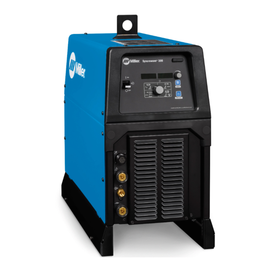
Syncrowave
Syncrowave 300
OWNER'S MANUAL
OM-284794E
2023-01
OM-284794D
Processes
TIG (GTAW) Welding
Processes
Processes
TIG (GTAW) Welding
Stick (SMAW) Welding
Stick (SMAW) Welding
Description
Description
208-240/480V Arc Welding Power
Source
208-240/480V Arc Welding Power Source
300
®
2021-01
Advertisement
Table of Contents
Troubleshooting

Related Manuals for Miller Syncrowave 300


Summary of Contents for Miller Syncrowave 300
- Page 1 Stick (SMAW) Welding Description Description 208-240/480V Arc Welding Power Source 208-240/480V Arc Welding Power Source Syncrowave ® Syncrowave 300 OWNER’S MANUAL For product information, Owner’s Manual translations, and more, visit www.MillerWelds.com For product information, Owner’s Manual translations, and more, visit...
- Page 2 We know you don’t have time to do it any other way. That’s why when Niels Miller first started building arc welders in 1929, he made sure his products offered long-lasting value and superior quality.
-
Page 3: Table Of Contents
TABLE OF CONTENTS SECTION 1 – SAFETY PRECAUTIONS – READ BEFORE USING..............1 Symbol Usage . - Page 4 TABLE OF CONTENTS SECTION 12 – SELECTING AND PREPARING A TUNGSTEN FOR DC OR AC WELDING WITH INVERTER MACHINES....43 12-1 Selecting Tungsten Electrode ..................43 12-2 Preparing Tungsten Electrode For DC Electrode Negative (DCEN) Welding Or AC Welding With Inverter Machines.
-
Page 5: Section 1 - Safety Precautions - Read Before Using
SECTION 1 – SAFETY PRECAUTIONS – READ BEFORE USING Protect yourself and others from injury—read, follow, and save these important safety precautions and operating instructions. 1-1. Symbol Usage DANGER! – Indicates a hazardous situation which, if not avoided, will result in death or serious injury. The possible hazards are shown in the adjoining symbols or explained in the text. - Page 6 HOT PARTS can burn. WELDING can cause fire or explosion. � Do not touch hot parts bare handed. � Allow cooling period before working on equipment. Welding on closed containers, such as tanks, drums, or pipes, can cause them to blow up. �...
-
Page 7: Additional Hazards For Installation, Operation, And Maintenance
� Never weld on a pressurized cylinder—explosion will result. CYLINDERS can explode if � Use only correct compressed gas cylinders, regulators, hoses, damaged. and fittings designed for the specific application; maintain them Compressed gas cylinders contain gas under high and associated parts in good condition. pressure. -
Page 8: California Proposition 65 Warnings
� To reduce possible interference, keep weld cables as short as ARC WELDING can cause possible, close together, and down low, such as on the floor. interference. � Locate welding operation 100 meters from any sensitive electronic equipment. � Electromagnetic energy can interfere with sensitive electronic equipment such as microprocessors, �... -
Page 9: Section 2 - Consignes De Sécurité - Lire Avant Utilisation
SECTION 2 – CONSIGNES DE SÉCURITÉ - LIRE AVANT UTILISATION Pour écarter les risques de blessure pour vous-même et pour autrui — lire, appliquer et ranger en lieu sûr ces consignes relatives aux précautions de sécurité et au mode opératoire. 2-1. - Page 10 � S’assurer que tous les panneaux et couvercles sont correctement LES ACCUMULATIONS DE GAZ en place. risquent de provoquer des blessures � Fixer le câble de retour de façon à obtenir un bon contact métal- ou même la mort. métal avec la pièce à souder ou la table de travail, le plus près possible de la soudure.
-
Page 11: Symboles De Dangers Supplémentaires En Relation Avec L'installation, Le Fonctionnement Et La Maintenance
� Brancher le câble de masse sur la pièce le plus près possible de � Les porteurs d’implants médicaux doivent consulter leur médecin la zone de soudage pour éviter le transport du courant sur une lon- et le fabricant du dispositif avant de s’approcher de la zone où se gue distance par des chemins inconnus éventuels en provoquant déroule du soudage à... -
Page 12: Proposition Californienne 65 Avertissements
� Affûter l'électrode au tungstène uniquement à la meuleuse dotée LIRE LES INSTRUCTIONS. de protecteurs. Cette manœuvre est à exécuter dans un endroit sûr lorsque l'on porte l'équipement homologué de protection du vi- � Lire et appliquer les instructions sur les étiquettes sage, des mains et du corps. -
Page 13: Informations Relatives Aux Cem
Safety in Welding, Cutting, and Allied Processes, CSA Standard Subpart N, Part 1910 Subpart Q, and Part 1926, Subpart J. Website: W117.2 from Canadian Standards Association. Website: www. csa- www.osha.gov. group.org. OSHA Important Note Regarding the ACGIH TLV, Policy Statement on the Uses of TLVs and BEIs. -
Page 14: Section 3 - Definitions
Reuse or recycle Waste Electrical and Electronic Equipment (WEEE) by disposing at a designated collection Some symbols are found only on CE products. Warning! Watch Out! There are possible hazards as shown by the symbols. Some symbols are found only on CE products. facility. - Page 15 Cutting sparks can cause fires. Have a fire extinguisher nearby, and have a watchperson ready to use it. Do not grip material near cutting path. � Complete Parts List is available at www.MillerWelds.com Safe1 Safe Do not fuel a hot engine. Do not fuel a hot engine.
- Page 16 machine or welding. Engine fuel plus flames or sparks can cause fire. Keep your head out of the fumes Engine fuel plus flames or sparks can cause fire. � Safe65 2012 06 Complete Parts List is available at www.MillerWelds.com Safe45 2012 05 Safe7 2017 04 Safe45 201 Hazardous voltage remains on input capacitors after power is turned...
-
Page 17: Miscellaneous Symbols And Definitions
� Complete Parts List is available at www.MillerWelds.com 3-2. Miscellaneous Symbols And Definitions Water (Coolant) Amperes Initial Amperage Output Rated Cooling Output Cooling Power (Coolers) Gas Tungsten Arc Rated Maximum Gas Input Welding (GTAW) Pressure (Coolers) Increase/Decrease Volts Gas Output Of Quantity Rated Welding Voltage Input... -
Page 18: Section 4 - Specifications
Information About Default Weld Parameters And Settings NOTICE – Each welding application is unique. Although certain Miller Electric products are designed to determine and default to certain typical welding parameters and settings based upon specific and relatively limited application variables input by the end user, such default settings are for reference purposes only;... -
Page 19: Cooler Specifications
� Complete Parts List is available at www.MillerWelds.com 4-5. Cooler Specifications � The correction factor on the cooling power at an ambient temperature of 104° F ( 40° C) is 0.625. Recirculating Coolant System For Water-Cooled GTAW Torches And GMAW Guns Use With Guns/Torches Rated Up To 600 Amperes Coolant Tank Capacity 3 gal (11.4 L) - Page 20 � Complete Parts List is available at www.MillerWelds.com B. Welding Power Source With Cart And Cooler Dimensions 43-7/8 in. (1114 mm) 20-1/2 in. (521 mm) 36 1/4 in. (921 mm) Weight 178 lb (80.1 kg) (Empty) Ref. 805617-A C. Mounting Options Dimensions 19-1/2 in.
-
Page 21: Duty Cycle And Overheating
� Complete Parts List is available at www.MillerWelds.com 4-8. Duty Cycle And Overheating Duty Cycle is percentage of 10 minutes that unit weld rated load without overheating. If unit overheats, output stops, a Help mes- sage is displayed (see Section 8-4), and cool- ing fan runs. -
Page 22: Section 5 - Installation
A complete Parts List is available at www.MillerWelds.com � Writers: Remember to move unit dimension and weight and rating la- Complete Parts List is available at www.MillerWelds.com bel location information to the appropriate sections. SECTION 5 – INSTALLATION 5-1. Selecting A Location 1-3. -
Page 23: Selecting Cable Sizes
� Complete Parts List is available at www.MillerWelds.com 5-2. Selecting Cable Sizes NOTICE – The Total Cable Length in Weld Circuit (see table below) is the combined length of both weld cables. For example, if the power source is 100 ft (30 m) from the workpiece, the total cable length in the weld circuit is 200 ft (2 cables x 100 ft). Use the 200 ft (60 m) column to determine cable size. -
Page 24: Connecting Weld Cables, Remote Control, And Shielding Gas
� Complete Parts List is available at www.MillerWelds.com 5-3. Connecting Weld Cables, Remote Control, And Shielding Gas Turn off power before connecting Front Panel to weld output terminals. Do not use worn, damaged, under- sized, or repaired cables. Connections 1 Remote Control Receptacle (see Section 5-9) 2 Electrode Weld Output Terminal For TIG (GTAW), connect torch to this... -
Page 25: Cooler Connections
� Complete Parts List is available at www.MillerWelds.com 5-4. Cooler Connections � Cart cooler optional equipment. 1 Electrode Weld Output Terminal Connect TIG torch to this terminal. 2 Gas Out Connection Connect TIG torch gas hose to gas out fitting. 3 Work Weld Output Terminal Connect work lead to this terminal. -
Page 26: Electrical Service Guide (1-Phase)
� Complete Parts List is available at www.MillerWelds.com 5-5. Electrical Service Guide (1-Phase) Failure to follow these electrical service guide recommendations could create an electric shock or fire hazard. These recommen- dations are for an individual branch circuit sized for the rated output and duty cycle of one welding power source. In individual branch circuit installations, the National Electrical Code (NEC) allows the receptacle or conductor rating to be less than the rating of the circuit protection device. -
Page 27: Connecting 1-Phase Input Power
� Complete Parts List is available at www.MillerWelds.com 5-7. Connecting 1-Phase Input Power Installation must meet all National and Local Codes—have only quali- fied persons make this installation. Disconnect and lockout/tagout in- put power before connecting input conductors from unit. Follow es- tablished procedures regarding... -
Page 28: Connecting 3-Phase Input Power
� Complete Parts List is available at www.MillerWelds.com 5-8. Connecting 3-Phase Input Power Installation must meet all National and Local Codes—have only quali- fied persons make this installation. Disconnect and lockout/tagout in- put power before connecting input = GND/PE Earth Ground conductors from unit. -
Page 29: Remote 14 Receptacle Information
� Complete Parts List is available at www.MillerWelds.com 5-9. Remote 14 Receptacle Information Remote 14 Socket Socket Information Contactor control +15 volts DC, referenced to G. 15 Volts DC Output Contact closure to A completes 15 volts DC con- Contactor tactor control circuit and enables output. - Page 30 � Complete Parts List is available at www.MillerWelds.com B. Installing Software Updates Syncrowave 300 Shown Ref. 805618-A Inserting card while welding will interrupt the Troubleshooting: � Software updates may reset machine welding process. back to default values. Indicator LED is blinking red: Error updating LED indicator blinks green when machine is software, or software is not compatible.
-
Page 31: Section 6 - Syncrowave Operation
SECTION 6 – SYNCROWAVE OPERATION 6-1. Syncrowave Controls 280539-B Displays actual rectified average voltage 8 Process Selector Control 1 Main Power Switch when voltage is present at the weld output terminals. It is also used to display parame- select following Use switch to turn machine on or off. -
Page 32: Accessing Process Menu: Ac Tig
150A 6-2. Accessing Process Menu: AC TIG 1 Menu Button Press Menu button to cycle through parame- ters that can be set. 2 Parameter Display 3 Setting Display 4 Amperage Adjustment Control Rotate Amperage Adjustment control to ad- 247222-D just parameter setting. 150A �... -
Page 33: Accessing Process Menu: Dc Tig And Dc Tig Pulse
6-3. Accessing Process Menu: DC TIG And DC TIG Pulse 1 Menu Button Press Menu button to cycle through parame- ters that can be set. 2 Parameter Display 3 Setting Display 4 Amperage Adjustment Control 150A Rotate Amperage Adjustment control to ad- just parameter setting. -
Page 34: Accessing Process Menu: Dc Stick
6-4. Accessing Process Menu: DC Stick 1 Menu Button Press Menu button to cycle through parame- ters that can be set. 2 Parameter Display 3 Setting Display 4 Amperage Adjustment Control 110A Rotate Amperage Adjustment control to ad- just parameter setting. �... -
Page 35: Accessing User Menu: Ac/Dc Tig And Dc Tig Pulse
6-5. Accessing User Menu: AC/DC TIG And DC TIG Pulse 1 Menu Button Press and hold Menu button for approxi- mately two seconds until USER MENU ap- pears to access machine configuration menus. Press Menu button to cycle through parameters that can be set. 2 Parameter Display 3 Setting Display MENU... -
Page 36: Accessing User Menu: Dc Stick
6-6. Accessing User Menu: DC Stick 1 Menu Button Press and hold Menu button for approxi- mately 2 seconds to access machine configu- ration menus. Use Menu button to cycle through parameters that can be set. 2 Parameter Display 3 Setting Display USER MENU 4 Amperage Adjustment Control... -
Page 37: Section 7 - Advanced Menu Functions
� Complete Parts List is available at www.MillerWelds.com SECTION 7 – ADVANCED MENU FUNCTIONS 7-1. Accessing Tech Menu 1 Menu Button Press and hold Menu button for approxi- mately four seconds to scroll past User Menu to Tech Menu. Use Menu button to cycle through parameters that can be set. -
Page 38: Summary Of Default And Pro-Set Parameters
� Complete Parts List is available at www.MillerWelds.com 7-2. Summary Of Default And Pro-Set Parameters AC TIG DC TIG DC PULSE TIG STICK Default Default Default Default (Pro- Process Menu Range Range Range Range (Pro-Set) (Pro-Set) (Pro-Set) Set) [BAL] Ball 30%, —... -
Page 39: Section 8 - Maintenance And Troubleshooting
A complete Parts List is available at www.MillerWelds.com SECTION 17 MAINTENANCE & TROUBLESHOO � Complete Parts List is available at www.MillerWelds.com SECTION 8 – MAINTENANCE AND TROUBLESHOOTING 17-1. Routine Maintenance 8-1. Routine Maintenance Repla Disconnect power before maintaining. � Maintain more often during severe conditions. A complete Parts List is available at www.MillerWelds.com A complete Parts List is available at www.MillerWelds.com SECTION 12... -
Page 40: Blowing Out Inside Of Unit
� Complete Parts List is available at www.MillerWelds.com 8-2. Blowing Out Inside Of Unit Do not remove case when blowing out inside of unit. To blow out unit, direct airflow through front and back louvers as shown. 8-3. Coolant Maintenance Disconnect input power before maintaining. -
Page 41: Voltmeter/Ammeter Display Messages
� Complete Parts List is available at www.MillerWelds.com 8-4. Voltmeter/Ammeter Display Messages � All directions are in reference to the front of the unit. All circuitry referred to is located inside the unit. Message Type Display Message Description Release Trigger [RELE] [ASE] / Remote 14 receptacle contactor control (Pins A-B) must be opened before [TRIG] [GER]... -
Page 42: Troubleshooting Table
� Complete Parts List is available at www.MillerWelds.com 8-5. Troubleshooting Table Trouble Remedy No weld output; unit completely Place line disconnect switch in On position (see Section 5-7 or 5-8). inoperative. Check and replace line fuse(s), if necessary, or reset circuit breaker (see Section 5-7 or 5-8). Check for proper input power connections (see Section 5-7 or 5-8). -
Page 43: Section 9 - Parts List
� Complete Parts List is available at www.MillerWelds.com SECTION 9 – PARTS LIST 9-1. Recommended Spare Parts Recommended Spare Parts Dia. Mkgs. Part No. Description Quantity 239494 Screen, Filter Lp Cyl 100 x 100 x 0.0045 SST A 043810 Coolant +When ordering a component originally displaying a precautionary label, the label should also be ordered. -
Page 44: Section 10 - Electrical Diagrams
SECTION 10 – ELECTRICAL DIAGRAMS Figure 10-1. Circuit Diagram OM-284794 Page 40... -
Page 45: Section 11 - High Frequency
SECTION 11 – HIGH FREQUENCY SECTION 1 HIGH FREQUENCY 11-1. Welding Processes Requiring High Frequency SECTION 1 HIGH FREQUENCY 1 High-Frequency Voltage TIG – helps arc jump air gap between torch and workpiece and/or stabilize the arc. 11-2. Installation Showing Possible Sources Of HF Interference 11, 12 Best Practices Not Followed 11, 12... -
Page 46: Recommended Installation To Reduce Hf Interference
11-3. Recommended Installation To Reduce HF Interference Best Practices Followed 50 ft (15 m) 50 ft (15 m) 1 High-Frequency Source (welding power Conduit Joint Bonding and Grounding Ground workpiece if required by codes. source with built-in HF or separate HF Electrically join (bond) all conduit sections 9 Nonmetal Building unit) -
Page 47: Section 12 - Selecting And Preparing A Tungsten For Dc Or Ac Welding With Inverter Machines
SECTION 12 – SELECTING AND PREPARING A TUNGSTEN FOR DC OR AC WELDING WITH INVERTER MACHINES 12-1. Selecting Tungsten Electrode Whenever possible and practical, use DC weld output instead of AC weld output. NOTICE – Wear clean gloves to prevent contamination of tungsten. A. -
Page 48: Preparing Tungsten Electrode For Dc Electrode Negative (Dcen) Welding Or Ac Welding With Inverter Machines
1-1. Preparing Tungsten Electrode For DC Electrode Negative (DCEN) Welding Or AC Welding With Inverter Machines Grinding the tungsten electrode produces dust and flying sparks which can cause injury and start fires. 12-2. Preparing Tungsten Electrode For DC Electrode Negative (DCEN) Welding Or AC Use local exhaust (forced ventilation) at the grinder or wear an approved respirator. -
Page 49: Section 13 - Tig Procedures
SECTION 5 TIG PROCEDURES SECTION 13 – TIG PROCEDURES SECTION 5 TIG PROCEDURES SECTION 5 TIG PROCEDURES Arc And HF TIG Start Procedures 13-1. Lift-Arc And HF TIG Start Procedures Arc And HF TIG Start Procedures Arc And HF TIG Start Procedures Lift-Arc Start Lift-Arc Start Method When Lift-Arc... -
Page 50: Section 14 - Stick Welding (Smaw) Guidelines
SECTION 14 – STICK WELDING (SMAW) GUIDELINES 14-1. Electrode And Amperage Selection Chart 6010 DEEP 3/32 MIN. PREP, ROUGH HIGH SPATTER 6011 DEEP 6010 5/32 & 6013 EP,EN GENERAL 3/16 6011 7/32 SMOOTH, EASY, 7014 EP,EN FAST 1/16 LOW HYDROGEN, 7018 5/64 STRONG... - Page 51 Effective January 1, 2023 (Equipment with a serial number preface of ND or newer) This limited warranty supersedes all previous Miller warranties and is exclusive with no other guarantees or war- ranties expressed or implied. � CoolBelt, PAPR Blower, and PAPR Face...
- Page 52 Appleton, WI 54914 USA tact your distributor and/or equipment manu- facturer’s Transportation Department. International Headquarters–USA USA Phone: 920-735-4505 USA & Canada FAX: 920-735-4134 International FAX: 920-735-4125 For International Locations Visit www.MillerWelds.com ORIGINAL INSTRUCTIONS – PRINTED IN USA © Miller Electric Mfg. LLC 2023-01...
Need help?
Do you have a question about the Syncrowave 300 and is the answer not in the manual?
Questions and answers