Table of Contents
Troubleshooting

Related Manuals for Miller ST-24w


Summary of Contents for Miller ST-24w
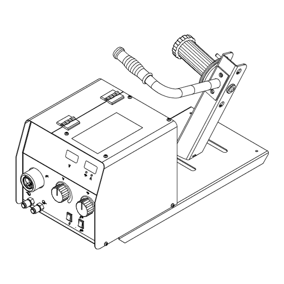
- Page 1 OM-287388B 2020-02 Processes MIG (GMAW) Welding Flux Cored (FCAW) Welding Description Wire Feeder ST-24w And ST-24wD For product information, Owner’s Manual translations, and more, visit www.MillerWelds.com...
- Page 2 From Miller to You Thank you and congratulations on choosing Miller. Now you can get the job done and get it done right. We know you don’t have time to do it any other way. That’s why when Niels Miller first started building arc welders in 1929, he made sure his products offered long-lasting value and superior quality.
-
Page 3: Table Of Contents
TABLE OF CONTENTS SECTION 1 − SAFETY PRECAUTIONS - READ BEFORE USING ....... . . 1-1. -
Page 5: Section 1 − Safety Precautions - Read Before Using
SECTION 1 − SAFETY PRECAUTIONS - READ BEFORE USING som 2020−02 Protect yourself and others from injury — read, follow, and save these important safety precautions and operating instructions. 1-1. Symbol Usage DANGER! − Indicates a hazardous situation which, if Indicates special instructions. - Page 6 D Do not cut or weld on tire rims or wheels. Tires can explode if heat- FUMES AND GASES can be hazardous. ed. Repaired rims and wheels can fail. See OSHA 29 CFR 1910.177 listed in Safety Standards. D Do not weld on containers that have held combustibles, or on Welding produces fumes and gases.
-
Page 7: Additional Hazards For Installation, Operation, And Maintenance
D Never weld on a pressurized cylinder − explosion will result. CYLINDERS can explode if damaged. D Use only correct compressed gas cylinders, regulators, hoses, and fittings designed for the specific application; maintain them Compressed gas cylinders contain gas under high and associated parts in good condition. -
Page 8: California Proposition 65 Warnings
H.F. RADIATION can cause interference. ARC WELDING can cause interference. D High-frequency (H.F.) can interfere with radio D Electromagnetic energy can interfere with navigation, safety services, computers, and sensitive electronic equipment such as communications equipment. computers and computer-driven equipment such as robots. D Have only qualified persons familiar with electronic equipment D Be sure all equipment in the welding area is electromagnetically perform this installation. -
Page 9: Section 2 − Definitions
SECTION 2 − DEFINITIONS 2-1. Additional Safety Symbols And Definitions Some symbols are found only on CE products. Warning! Watch Out! There are possible hazards as shown by the symbols. Safe1 2012−05 Wear dry insulating gloves. Do not touch electrode (wire) with bare hand. Do not wear wet or damaged gloves. Safe57 2017−04 Disconnect input plug or power before working on machine. - Page 10 Use forced ventilation or local exhaust to remove the fumes. Safe60 2012−06 Use ventilating fan to remove fumes. Safe61 2012−06 Keep flammables away from welding. Do not weld near flammables. Safe62 2012−06 Welding sparks can cause fires. Have a fire extinguisher nearby, and have a watchperson ready to use it. Safe63 2012−06 Do not weld on drums or any closed containers.
-
Page 11: Miscellaneous Symbols And Definitions
2-2. Miscellaneous Symbols And Definitions Alternating Current Input Positive Circuit Breaker Remote Gas Metal Arc Primary Current Welding (GMAW) Duty Cycle Water (Coolant) Output Gas Input Wire Feed Amperes Voltage Input Degree Of Line Connection Protection Rated Current Primary Voltage Wire Run-In Speed Purge Read Instructions... -
Page 12: Section 3 − Specifications
SECTION 3 − SPECIFICATIONS 3-1. Serial Number And Rating Label Location The serial number and rating information for this product is located on back of control box. Use rating label to determine input power requirements and/or rated output. For future reference, write serial number in space provided on back cover of this manual. 3-2. -
Page 13: Section 4 − Installation
SECTION 4 − INSTALLATION 4-1. Selecting A Location Do not put feeder where welding wire hits cylinder. Wire feeder shown is repre- sentative only and may not reflect actual unit. Wire Feeder Rubber Feet Choose slot that allows all rubber feet to sit securely on top of welding power source. -
Page 14: Equipment Connection Diagrams
4-2. Equipment Connection Diagrams CV Welding Power Source With 24 VAC Power CV Welding Power Source Without 24 VAC Power 115 Volts AC /24 Volts AC Power Adapter 14-Pin Control Cord Weld Cable (Required) Work 115VAC Contactor 4-3. 14-Pin Receptacle, Shielding Gas, And Weld Cable Connection Gas Connections Shielding gas pressure not to exceed 0.500 Mpa (72 PSI). -
Page 15: 14-Pin Receptacle Information
4-4. 14-Pin Receptacle Information Pin* Pin Information 24 volts AC with respect to pin G. Contact closure to A completes 24 volts AC contactor control circuit. Circuit common for 24 volts AC circuit. +10 volts DC output to remote control with respect to pin D. Remote control circuit common. -
Page 16: Optional Meter Circuit Board Settings
4-6. Optional Meter Circuit Board Settings Meter Circuit Board DIP Switch S2 Set DIP switch S2 for type of welding power source, and desired wire feed speed display (see illustration). Reinstall wrapper. X Indicates switch position does not affect specified function. Means switch must be in this position. -
Page 17: Installing Wire Guide And Drive Roll
4-7. Installing Wire Guide And Drive Roll Inlet Wire Guide Securing Screw Inlet Wire Guide Loosen screw. Slide tip as close to drive rolls as possible without touching. Tighten screw. Drive Roll The drive roll consists of two differ- ent sized grooves. The stamped markings on the end surface of the drive roll refers to the groove on the opposite side of the drive roll. -
Page 18: Installing And Threading Welding Wire
4-8. Installing And Threading Welding Wire Retaining Ring Hub Tension Adjustment Nut If necessary, move hub on support for use of a different size wire spool. Remove retaining ring, and install spool so hub pin fits spool hole. Reinstall retaining ring. Adjust tension nut so wire is taut when wire feed stops. -
Page 19: Installing Optional Spool Cover
4-9. Installing Optional Spool Cover Spool Cover Round Head Screw Loosen screw to remove spool hub from the spool support bracket. Open the spool cover and place it on the spool support bracket. Use round head screws to install spool cover. -
Page 20: Section 5 − Operation
Optional Remote Voltage Control Use control to set welding power source voltage at the wire feeder. Numbers are for reference only. ST-24w Wire Speed Control Gas Purge Switch Press Gas Purge Switch to ener- gize gas valve to purge air from gun, or adjust gas regulator. -
Page 21: Optional Side Panel Controls
5-2. Optional Side Panel Controls Wire Jog Control Use Jog position to momentarily feed welding wire at speed set on Wire Speed control without ener- gizing welding circuit or shielding gas valve. Wire Run-In Control Use control to set wire feed speed before arc is initiated. -
Page 22: Overload Protection
6-2. Overload Protection Turn Off unit and welding power source. Circuit Breaker CB1 CB1 protects wire feeder from overload. Correct problem and manually reset breaker. Ref. 805 227-A 6-3. Troubleshooting Trouble Remedy Wire does not feed, unit completely Turn Power switch On. inoperative. -
Page 23: Section 7 − Electrical Diagram
SECTION 7 − ELECTRICAL DIAGRAM (210 937-A) 956.142.625 Figure 7-1. Circuit Diagram For Wire Feeder With Optional Equipment OM-287388 Page 19... -
Page 24: Section 8 − Parts List
SECTION 8 − PARTS LIST Fig. 8-2 956.142.644-_3-B Figure 8-1. Main Assembly OM-287388 Page 20... - Page 25 ... 356029271 Nameplate, Front ST-24w ....... .
- Page 26 956.142.644_ Figure 8-2. Drive Assembly, Wire (4 Drive Roll ) OM-287388 Page 22...
- Page 27 Item Dia. Part Mkgs. Description Quantity Figure 8-2. Drive Assembly, Wire(4 Drive Roll) ..057010051 . . . Motor, Gear 24 V 100W ..........
- Page 28 Table 8-1. Drive Roll And Wire Guide Kits (4 Drive Roll) Base selection of drive rolls upon the following recommended usages: 1. V-Grooved rolls for hard wire. 2. U-Grooved rolls for soft and soft shelled cored wires. 3. U-Cogged rolls for extremely soft shelled wires (usually hard surfacing types). 4.
- Page 29 Notes Work like a Pro! Pros weld and cut safely. Read the safety rules at the beginning of this manual.
- Page 30 Notes Work like a Pro! Pros weld and cut safely. Read the safety rules at the beginning of this manual.
- Page 31 Effective January 1, 2020 (Equipment with a serial number preface of NA or newer) This limited warranty supersedes all previous Miller warranties and is exclusive with no other guarantees or warranties expressed or implied. LIMITED WARRANTY − Subject to the terms and conditions Positioners and Controllers below, Miller Electric Mfg.
- Page 32 File a claim for loss or damage during Fax: +31 (0) 186 640 880 shipment. For assistance in filing or settling claims, contact your distributor and/or equipment manufacturer’s Transportation Department. © ORIGINAL INSTRUCTIONS − PRINTED IN USA 2020 Miller Electric Mfg. LLC 2020−01...
Need help?
Do you have a question about the ST-24w and is the answer not in the manual?
Questions and answers