Table of Contents
Troubleshooting

Related Manuals for Miller Syncrowave 400


Summary of Contents for Miller Syncrowave 400
- Page 1 OM-285160B 2021-03 Processes Processes TIG (GTAW) Welding Stick (SMAW) Welding Description 208-240/480V Arc Welding Power Source Syncrowave 400 For product information, Owner’s Manual translations, and more, visit www.MillerWelds.com...
- Page 2 We know you don’t have time to do it any other way. That’s why when Niels Miller first started building arc welders in 1929, he made sure his products offered long-lasting value and superior quality.
-
Page 3: Table Of Contents
TABLE OF CONTENTS SECTION 1 − SAFETY PRECAUTIONS - READ BEFORE USING ....... . . 1-1. - Page 4 TABLE OF CONTENTS SECTION 8 − MAINTENANCE AND TROUBLESHOOTING ........8-1.
-
Page 5: Section 1 − Safety Precautions - Read Before Using
SECTION 1 − SAFETY PRECAUTIONS - READ BEFORE USING som 2020−02 Protect yourself and others from injury — read, follow, and save these important safety precautions and operating instructions. 1-1. Symbol Usage DANGER! − Indicates a hazardous situation which, if Indicates special instructions. - Page 6 D Do not cut or weld on tire rims or wheels. Tires can explode if heat- FUMES AND GASES can be hazardous. ed. Repaired rims and wheels can fail. See OSHA 29 CFR 1910.177 listed in Safety Standards. D Do not weld on containers that have held combustibles, or on Welding produces fumes and gases.
-
Page 7: Additional Hazards For Installation, Operation, And Maintenance
D Never weld on a pressurized cylinder − explosion will result. CYLINDERS can explode if damaged. D Use only correct compressed gas cylinders, regulators, hoses, and fittings designed for the specific application; maintain them Compressed gas cylinders contain gas under high and associated parts in good condition. -
Page 8: California Proposition 65 Warnings
H.F. RADIATION can cause interference. ARC WELDING can cause interference. D High-frequency (H.F.) can interfere with radio D Electromagnetic energy can interfere with navigation, safety services, computers, and sensitive electronic equipment such as communications equipment. computers and computer-driven equipment such as robots. D Have only qualified persons familiar with electronic equipment D Be sure all equipment in the welding area is electromagnetically perform this installation. -
Page 9: Section 2 − Consignes De Sécurité − Lire Avant Utilisation
SECTION 2 − CONSIGNES DE SÉCURITÉ − LIRE AVANT UTILISATION som_2020−02_fre Pour écarter les risques de blessure pour vous−même et pour autrui — lire, appliquer et ranger en lieu sûr ces consignes relatives aux précautions de sécurité et au mode opératoire. 2-1. - Page 10 D Déplacer toutes les substances inflammables à une distance de LES PIÈCES CHAUDES peuvent 10,7 m de l’arc de soudage. En cas d’impossibilité les recouvrir provoquer des brûlures. soigneusement avec des protections homologués. D Ne pas toucher à mains nues les parties chaudes. D Ne pas souder dans un endroit là...
-
Page 11: Dangers Supplémentaires En Relation Avec L'installation, Le Fonctionnement Et La Maintenance
D Protéger les bouteilles de gaz comprimé d’une chaleur excessive, Les CHAMPS ÉLECTROMAGNÉTIQUES (CEM) des chocs mécaniques, des dommages physiques, du laitier, des peuvent affecter les implants médicaux. flammes ouvertes, des étincelles et des arcs. D Placer les bouteilles debout en les fixant dans un support station- D Les porteurs de stimulateurs cardiaques et naire ou dans un porte-bouteilles pour les empêcher de tomber ou autres implants médicaux doivent rester à... -
Page 12: Proposition Californienne 65 Avertissements
D Effectuer régulièrement le contrôle et l’entretien de l’installation. LIRE LES INSTRUCTIONS. D Maintenir soigneusement fermés les portes et les panneaux des sources de haute fréquence, maintenir les éclateurs à une distan- D Lire et appliquer les instructions sur les ce correcte et utiliser une terre et un blindage pour réduire les étiquettes et le Mode d’emploi avant l’instal- interférences éventuelles. -
Page 13: Section 3 − Definitions
A complete Parts List is available at www.MillerWelds.com SECTION 3 − DEFINITIONS 3-1. Additional Safety Symbols And Definitions Some symbols are found only on CE products. Warning! Watch Out! There are possible hazards as shown by the symbols. Safe1 2012−05 Wear dry insulating gloves. - Page 14 A complete Parts List is available at www.MillerWelds.com Do not weld on drums or any closed containers. Safe16 2017−04 Do not remove or paint over (cover) the label. Safe20 2017−04 When power is applied failed parts can explode or cause other parts to explode. Safe26 2012−05 Flying pieces of parts can cause injury.
- Page 15 A complete Parts List is available at www.MillerWelds.com Hazardous voltage remains on input capacitors after power is turned off. Do not touch fully charged capacitors. Always wait 60 seconds after power is turned off before working on unit, AND check input ca- pacitor voltage, and be sure it is near 0 before touching any parts.
-
Page 16: Miscellaneous Symbols And Definitions
A complete Parts List is available at www.MillerWelds.com 3-2. Miscellaneous Symbols And Definitions Maximum Alternating Amperes Effective Supply Current 1eff Current Gas Tungsten Arc Water (Coolant) Rated No Load Welding (GTAW) Input Voltage (OCV) Shielded Metal Water (Coolant) Rated Cooling Arc Welding Output Power (Coolers) -
Page 17: Section 4 − Specifications
4-3. Information About Default Weld Parameters And Settings NOTICE − Each welding application is unique. Although certain Miller Electric products are designed to determine and default to certain typical welding parameters and settings based upon specific and relatively limited application variables input by the end user, such default settings are for reference purposes only;... -
Page 18: Cooler Specifications
A complete Parts List is available at www.MillerWelds.com Current Draw (A) Output Ratings Input Power At Rate Input Voltages (V) Process Current Duty Voltage (V) Phase 208V 240V 480V Cycle Power Draw (W) − − − Idle OCV − − −... -
Page 19: Duty Cycle And Overheating
A complete Parts List is available at www.MillerWelds.com 4-7. Duty Cycle And Overheating Duty Cycle is percentage of 10 minutes that unit can weld at rated load without overheating. If unit overheats, output stops, a Help message is displayed (see Section 8-2), and cooling fan runs. Wait fifteen minutes for unit to cool. -
Page 20: Section 5 − Installation
A complete Parts List is available at www.MillerWelds.com SECTION 5 − INSTALLATION 5-1. Selecting A Location Movement Do not move or operate unit where it could tip. Location And Airflow Special installation may be required where gasoline or volatile liquids are present − see NEC Article 511 or CEC Section 20. -
Page 21: Dimensions, Weights, And Mounting Options
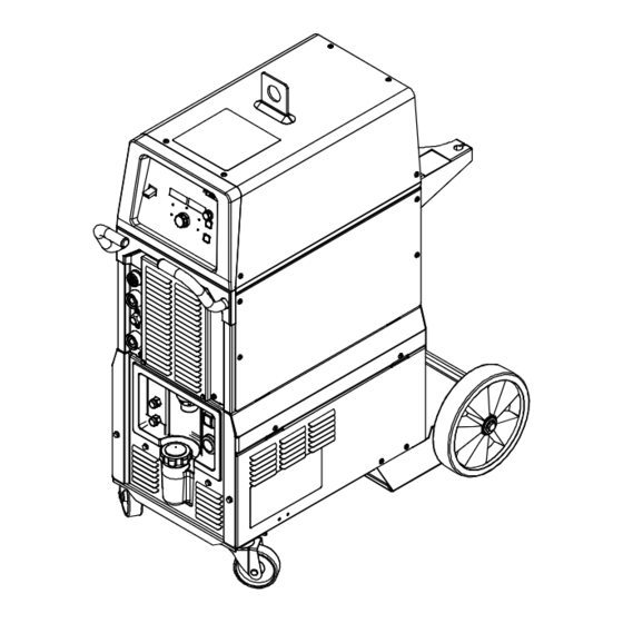
A complete Parts List is available at www.MillerWelds.com 5-2. Dimensions, Weights, And Mounting Options A. Welding Power Source Dimensions 29-3/8 in. (746 mm) 15 in. (381 mm) 24-5/8 in. (625 mm) Weight 131 lb (59.4 kg) Ref. 805617-A B. Welding Power Source With Cart And Cooler Dimensions 43-7/8 in. -
Page 22: Selecting Cable Sizes
A complete Parts List is available at www.MillerWelds.com C. Mounting Options Dimensions 19-1/2 in. (495 mm) 2 in. (51 mm) 4 x .500 in. Dia. (13 mm) Base 1 in. (25 mm) 13 in. (330 mm) 805620-A 5-3. Selecting Cable Sizes* NOTICE −... -
Page 23: Connecting Weld Cables, Remote Control, And Shielding Gas
A complete Parts List is available at www.MillerWelds.com 5-4. Connecting Weld Cables, Remote Control, And Shielding Gas Turn off power before connect- ing to weld output terminals. Do not use worn, damaged, undersized, or repaired cables. Connections 1. Remote Control Receptacle (See Section 5-9) 2. -
Page 24: Cooler Connections
A complete Parts List is available at www.MillerWelds.com 5-5. Cooler Connections Cart and cooler are optional equipment. 1. Electrode Weld Output Terminal Connect TIG torch to this terminal. 2. Gas Out Connection Connect TIG torch gas hose to gas out fitting. -
Page 25: Electrical Service Guide
A complete Parts List is available at www.MillerWelds.com 5-6. Electrical Service Guide Elec Serv 2020−02 A. Electrical Service Guide For Three-Phase Operation Failure to follow these electrical service guide recommendations could create an electric shock or fire hazard. These recommenda- tions are for a dedicated circuit sized for the rated output and duty cycle of the welding power source. - Page 26 A complete Parts List is available at www.MillerWelds.com B. Electrical Service Guide For Single-Phase Operation Elec Serv 2020−20 Failure to follow these electrical service guide recommendations could create an electric shock or fire hazard. These recommenda- tions are for a dedicated circuit sized for the rated output and duty cycle of the welding power source. In dedicated circuit installations, the National Electrical Code (NEC) allows the receptacle or conductor rating to be less than the rating of the circuit protection device.
-
Page 27: Connecting Three-Phase Input Power
A complete Parts List is available at www.MillerWelds.com 5-7. Connecting Three-Phase Input Power = GND/PE Earth Ground Tools Needed: input2 2012−05 − 803766-C / Ref. 805618-A OM-285160 Page 23... - Page 28 A complete Parts List is available at www.MillerWelds.com 5-7. Connecting Three-Phase Input Power (Continued) See rating label on unit and check input Connect green or green/yellow grounding Installation must meet all National voltage available at site. conductor to disconnect device grounding and Local Codes −...
-
Page 29: Connecting Single-Phase Input Power
A complete Parts List is available at www.MillerWelds.com 5-8. Connecting Single-Phase Input Power Installation must meet all National and Local Codes − have only quali- fied persons make this installation. Disconnect and lockout/tagout in- put power before connecting input conductors from unit. Follow es- tablished procedures regarding the installation and removal of lockout/tagout devices. -
Page 30: Remote 14 Receptacle Information
A complete Parts List is available at www.MillerWelds.com 5-9. Remote 14 Receptacle Information Socket Socket Information Contactor control +15 volts DC, referenced to G. 15 VOLTS DC C L N OUTPUT Contact closure to A completes 15 volts DC CONTACTOR contactor control circuit and enables output. -
Page 31: Software Updates
A complete Parts List is available at www.MillerWelds.com 5-10. Software Updates A. Reasons For Downloads Of Software Updates • To get the latest feature and software improvements with future software updates. • For all circuit board replacements, a software update is required to ensure proper unit operation. •... - Page 32 Indicator LED is continuous red: to the card, and the meter displays Cannot read card. Card might be go blank. The update time may vary bad. Syncrowave 400 Shown Ref. 805630-A Notes OM-285160 Page 28...
-
Page 33: Section 6 − Syncrowave Operation
A complete Parts List is available at www.MillerWelds.com SECTION 6 − SYNCROWAVE OPERATION 6-1. Syncrowave Controls MENU PRO-SET 285145-A 1. Main Power Switch Displays actual rectified average voltage 8. Process Selector when voltage is present at the weld output Use to select one of the following Use switch to turn machine on or off. -
Page 34: Accessing Process Menu: Ac Tig
A complete Parts List is available at www.MillerWelds.com 6-2. Accessing Process Menu: AC TIG 1. Menu Button Press Menu button to cycle through parameters that can be set. 2. Parameter Display 3. Setting Display 4. Amperage Adjustment Control Rotate Amperage Adjustment Con- trol to adjust parameter setting. -
Page 35: Accessing Process Menu: Dc Tig And Dc Tig Pulse
A complete Parts List is available at www.MillerWelds.com 6-3. Accessing Process Menu: DC TIG And DC TIG Pulse 1. Menu Button Press Menu button to cycle through paramet- ers that can be set. 2. Parameter Display 3. Setting Display 4. Amperage Adjustment Control Rotate Amperage Adjustment Control to adjust parameter setting. -
Page 36: Accessing Process Menu: Dc Stick
A complete Parts List is available at www.MillerWelds.com 6-4. Accessing Process Menu: DC Stick 1. Menu Button Press Menu button to cycle through paramet- ers that can be set. 2. Parameter Display 3. Setting Display 4. Amperage Adjustment Control Rotate Amperage Adjustment Control to ad- just parameter setting. -
Page 37: Accessing User Menu: Ac/Dc Tig And Dc Tig Pulse
A complete Parts List is available at www.MillerWelds.com 6-5. Accessing User Menu: AC/DC TIG And DC TIG Pulse 1. Menu Button Press and hold Menu button for ap- proximately two seconds until USER MENU appears to access machine configuration menus. Press Menu button to cycle through parameters that can be set. -
Page 38: Accessing User Menu: Dc Stick
A complete Parts List is available at www.MillerWelds.com 6-6. Accessing User Menu: DC Stick 1. Menu Button Press and hold Menu button for ap- proximately 2 seconds to access machine configuration menus. Use Menu button to cycle through para- meters that can be set. 2. -
Page 39: Section 7 − Advanced Menu Functions
A complete Parts List is available at www.MillerWelds.com SECTION 7 − ADVANCED MENU FUNCTIONS 7-1. Accessing Tech Menu 1. Menu Button Press and hold Menu button for ap- proximately four seconds to scroll past User Menu to Tech Menu. Use Menu button to cycle through parameters that can be set. -
Page 40: Summary Of Default And Pro-Set Parameters
A complete Parts List is available at www.MillerWelds.com 7-2. Summary Of Default And Pro-Set Parameters AC TIG DC TIG DC PULSE TIG STICK Process Menu Default Default Default Default Range Range Range Range (Pro-Set) (Pro-Set) (Pro-Set) (Pro-Set) Ball 30%, [BAL] −... -
Page 41: Section 8 − Maintenance And Troubleshooting
A complete Parts List is available at www.MillerWelds.com SECTION 8 − MAINTENANCE AND TROUBLESHOOTING 8-1. Routine Maintenance Disconnect power before maintaining. Maintain more often during severe conditions. A. Welding Power Source n = Check Z = Change ~ = Clean Δ... -
Page 42: Voltmeter/Ammeter Display Messages
A complete Parts List is available at www.MillerWelds.com 8-2. Voltmeter/Ammeter Display Messages Release Trigger Latching Errors: CHEK INPT RELE WELD CABL TRIG Errors requiring power off to reset. O.M. Un Short Output COOL HORT UN S Not Valid OUTP VALD Over Temperature Error Software Not Valid OVER TEMP... -
Page 43: Troubleshooting Table
A complete Parts List is available at www.MillerWelds.com 8-3. Troubleshooting Table Trouble Remedy No weld output; unit completely Place line disconnect switch in On position (see Section 5-7 or 5-8). inoperative. Check and replace line fuse(s), if necessary, or reset circuit breaker (see Section 5-7 or 5-8). Check for proper input power connections (see Section 5-7 or 5-8). -
Page 44: Blowing Out Inside Of Unit
A complete Parts List is available at www.MillerWelds.com 8-4. Blowing Out Inside of Unit Do not remove case when blowing out inside of unit. To blow out unit, direct airflow through front and back louvers as shown. Ref 805617-A 8-5. Coolant Maintenance Disconnect input power... -
Page 45: Section 9 − Parts List
A complete Parts List is available at www.MillerWelds.com SECTION 9 − PARTS LIST 9-1. Recommended Spare Parts Part Description Quantity Recommended Spare Parts ....239494 . -
Page 46: Section 10 − Electrical Diagram
A complete Parts List is available at www.MillerWelds.com SECTION 10 − ELECTRICAL DIAGRAM 285165-B Figure 10-1. Circuit Diagram OM-285160 Page 42... -
Page 47: Section 11 − High Frequency
SECTION 11 − HIGH FREQUENCY 11-1. Welding Processes Requiring High Frequency 1. High-Frequency Voltage TIG − helps arc jump air gap between torch and workpiece and/ or stabilize the arc. high_freq 2018-01 11-2. Installation Showing Possible Sources Of HF Interference Weld Zone 11, 12 50 ft... -
Page 48: Recommended Installation To Reduce Hf Interference
11-3. Recommended Installation To Reduce HF Interference Weld Zone 50 ft (15 m) 50 ft (15 m) Ground all metal ob- jects and all wiring in welding zone using #12 AWG wire. Ground workpiece if required by Nonmetal codes. Building Best Practices Followed Metal Building Ref. -
Page 49: With Inverter Machines
SECTION 12 − SELECTING AND PREPARING A TUNGSTEN FOR DC OR AC WELDING WITH INVERTER MACHINES gtaw_Inverter_2018-01 Whenever possible and practical, use DC weld output instead of AC weld output. 12-1. Selecting Tungsten Electrode ( Wear Clean Gloves To Prevent Contamination Of Tungsten A. -
Page 50: Preparing Tungsten Electrode For Dc Electrode Negative (Dcen) Welding
12-2. Preparing Tungsten Electrode For DC Electrode Negative (DCEN) Welding Or AC Welding With Inverter Machines Grinding the tungsten electrode produces dust and flying sparks which can cause injury and start fires. Use local exhaust (forced ventilation) at the grinder or wear an approved respirator. Read MSDS for safety information. -
Page 51: Section 13 − Tig Procedures
SECTION 13 − TIG PROCEDURES gtaw_Inverter_2011-06 For additional resources on welding, visit http://www.millerwelds.com/resources/welding-resources/ 13-1. Lift-Arc And HF TIG Start Procedures Lift-Arc Start When Lift-Arct button light is On, start arc as follows: 1. TIG Electrode 2. Workpiece Touch tungsten electrode to work- piece at weld start point, enable out- put and shielding gas with torch trig- ger, foot control, or hand control. -
Page 52: Section 14 − Stick Welding (Smaw) Electrode And Amperage Selection Chart
SECTION 14 − STICK WELDING (SMAW) ELECTRODE AND AMPERAGE SELECTION CHART 6010 DEEP 3/32 MIN. PREP, ROUGH HIGH SPATTER 6011 DEEP 6010 5/32 & 6013 EP,EN GENERAL 3/16 6011 7/32 SMOOTH, EASY, 7014 EP,EN FAST 1/16 LOW HYDROGEN, 7018 5/64 STRONG 3/32 SMOOTH, EASY,... - Page 53 Notes...
- Page 54 Notes MATERIAL THICKNESS REFERENCE CHART 24 Gauge (.025 in.) 22 Gauge (.031 in.) 20 Gauge (.037 in.) 18 Gauge (.050 in.) 16 Gauge (.063 in.) 14 Gauge (.078 in.) 1/8 in. (.125 in.) 3/16 in. (.188 in.) 1/4 in. (.25 in.) 5/16 in.
- Page 55 Effective January 1, 2021 (Equipment with a serial number preface of NB or newer) This limited warranty supersedes all previous Miller warranties and is exclusive with no other guarantees or warranties expressed or implied. LIMITED WARRANTY − Subject to the terms and conditions...
- Page 56 Contact the Delivering Carrier to: File a claim for loss or damage during shipment. For assistance in filing or settling claims, contact your distributor and/or equipment manufacturer’s Transportation Department. © ORIGINAL INSTRUCTIONS − PRINTED IN USA 2021 Miller Electric Mfg. LLC 2021−01...
Need help?
Do you have a question about the Syncrowave 400 and is the answer not in the manual?
Questions and answers