Sign In
Upload
Download
Table of Contents
Contents
Add to my manuals
Delete from my manuals
Share
URL of this page:
HTML Link:
Bookmark this page
Add
Manual will be automatically added to "My Manuals"
Print this page
×
Bookmark added
×
Added to my manuals
Manuals
Brands
Miller Manuals
Welding System
SRH-333
Owner's manual
Miller SRH-333 Owner's Manual
Hide thumbs
Also See for SRH-333
:
Owner's manual
(31 pages)
1
2
Table Of Contents
3
4
5
6
7
8
9
10
11
12
13
14
15
16
17
18
19
20
21
22
23
24
25
26
27
28
29
30
31
32
33
34
35
36
37
38
39
40
page
of
40
Go
/
40
Contents
Table of Contents
Troubleshooting
Bookmarks
Table of Contents
Table of Contents
Section 1 - Safety Precautions
Symbol Usage
Arc Welding Hazards
Additional Symbols for Installation, Operation, and Maintenance
Principal Safety Standards
EMF Information
Section 1 - Consignes de Securite
Signification des Symboles
Dangers Relatifs au Soudage à L'arc
Dangers Supplémentaires en Relation Avec L'installation, le Fonctionnement et la Maintenance
Principales Normes de Sécurité
Information Sur les Champs Électromagnétiques
Section 2 - Definitions
General Precautionary Label
Input Connection Label
Electric Shock and Airflow Label
Nameplate Safety Symbols
Manufacturer's Rating Labels for CE Products
Symbols and Definitions
Section 3 - Installation
Duty Cycle and Overheating
Selecting a Location
Tipping
Selecting and Preparing Weld Output Cables
Connecting to Weld Output Terminals
3-10.Remote Amperage Control Receptacle
3-12.Connecting Input Power
Section 4 - Operation
Controls
Amperage Adjustment Control
Remote Amperage Switch
Power Switch
Ammeter and Voltmeter (Optional)
Section 5 - Maintenance & Troubleshooting
Overload Protection
Section 6 - Electrical Diagram
Section 7 - Parts List
Options and Accessories
Advertisement
Quick Links
1
3-12.Connecting Input Power
2
Section 7 - Parts List
Download this manual
Visit our website at
www.MillerWelds.com
SRH-333, SRH-444 And SRH-500
OM-2230
199 954A
July 2000
Processes
Stick (SMAW) Welding
Air Plasma Cutting
and Gouging
Air Carbon Arc (CAC-A)
Cutting and Gouging
Submerged (SAW) Welding
Description
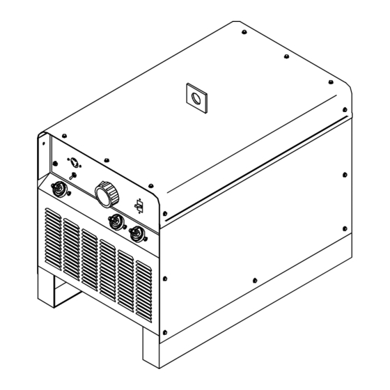
Arc Welding Power Source
Table of
Contents
Previous
Page
Next
Page
1
2
3
4
5
Advertisement
Table of Contents
Need help?
Do you have a question about the SRH-333 and is the answer not in the manual?
Ask a question
Questions and answers
Related Manuals for Miller SRH-333
Welding System Miller SRH-222 Owner's Manual
(31 pages)
Welding System Miller SRH-444 Owner's Manual
Arc welding power source (36 pages)
Welding System Miller SRH-666 Owner's Manual
(31 pages)
Welding System Miller SRH-555 Owner's Manual
(31 pages)
Welding System Miller SRH-500 Owner's Manual
(40 pages)
Welding System Miller SRH 2000 CHANTIER Owner's Manual
(24 pages)
Welding System Miller Spectrum Lynx Owner's Manual
Air plasma cutter (28 pages)
Welding System Miller ST 44 Series Wire Feeder Owner's Manual
(28 pages)
Welding System Miller PowCon Arc Stud 625 Owner's Manual
(44 pages)
Welding System Miller Syncrowave 300 Owner's Manual
(52 pages)
Welding System Miller Blue Star 185 Owner's Manual
(56 pages)
Welding System Miller Syncrowave 210 Owner's Manual
(56 pages)
Welding System Miller Gold Star Series Owner's Manual
Ce and non-ce arc welding power source (48 pages)
Welding System Miller STH 160 Owner's Manual
(36 pages)
Welding System Miller Shielded Metal Arc Welding Manuallines
(28 pages)
Welding System Miller S-22P8 Owner's Manual
(25 pages)
This manual is also suitable for:
Srh-444
Srh-500
Table of Contents
Print
Rename the bookmark
Delete bookmark?
Delete from my manuals?
Login
Sign In
OR
Sign in with Facebook
Sign in with Google
Upload manual
Upload from disk
Upload from URL


Need help?
Do you have a question about the SRH-333 and is the answer not in the manual?
Questions and answers