Miller Blue Star 185 Owner's Manual
Hide thumbs
Also See for Blue Star 185:
- Manual (4 pages) ,
- Application manual (16 pages) ,
- Owner's manual (60 pages)

Related Manuals for Miller Blue Star 185


Summary of Contents for Miller Blue Star 185
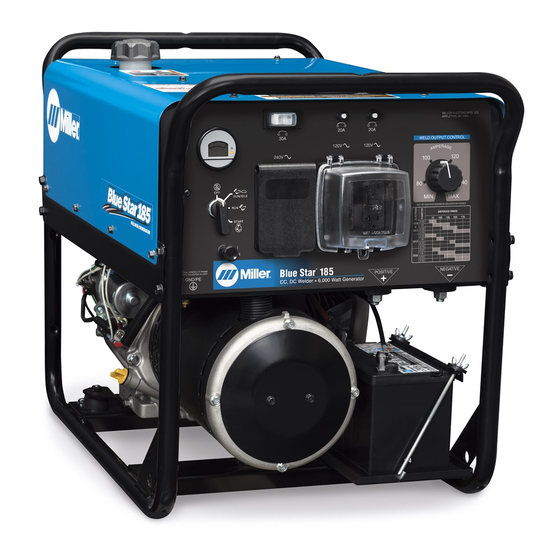
- Page 1 OM-267 212E 2016−02 Processes Stick (SMAW) Welding Description Engine Driven Welder/Generator Blue Star 185 File: Engine Drive Visit our website at www.MillerWelds.com...
- Page 2 We know you don’t have time to do it any other way. That’s why when Niels Miller first started building arc welders in 1929, he made sure his products offered long-lasting value and superior quality.
-
Page 3: Table Of Contents
TABLE OF CONTENTS SECTION 1 − SAFETY PRECAUTIONS − READ BEFORE USING ....... . . 1-1. - Page 4 TABLE OF CONTENTS SECTION 9 − TROUBLESHOOTING ............SECTION 10 −...
-
Page 5: Section 1 − Safety Precautions − Read Before Using
SECTION 1 − SAFETY PRECAUTIONS − READ BEFORE USING rom_2015−09 Protect yourself and others from injury — read, follow, and save these important safety precautions and operating instructions. 1-1. Symbol Usage DANGER! − Indicates a hazardous situation which, if Indicates special instructions. not avoided, will result in death or serious injury. - Page 6 D Be alert that welding sparks and hot materials from welding can FLYING METAL or DIRT can injure easily go through small cracks and openings to adjacent areas. eyes. D Watch for fire, and keep a fire extinguisher nearby. D Welding, chipping, wire brushing, and grinding D Be aware that welding on a ceiling, floor, bulkhead, or partition can cause sparks and flying metal.
-
Page 7: Engine Hazards
1-3. Engine Hazards EXHAUST SPARKS can cause fire. BATTERY EXPLOSION can injure. D Do not let engine exhaust sparks cause fire. D Always wear a face shield, rubber gloves, and D Use approved engine exhaust spark arrestor in protective clothing when working on a battery. required areas —... -
Page 8: Additional Symbols For Installation, Operation, And Maintenance
HOT METAL from air arc cutting and MOVING PARTS can injure. gouging can cause fire or explosion. D Keep away from moving parts such as fans, D Do not cut or gouge near flammables. belts and rotors. D Watch for fire; keep extinguisher nearby. D Keep all doors, panels, covers, and guards closed and securely in place. - Page 9 BATTERY CHARGING OUTPUT and BATTERY STATIC (ESD) can damage PC boards. EXPLOSION can injure. D Put on grounded wrist strap BEFORE handling Battery charging not present on all models. boards or parts. D Use proper static-proof bags and boxes to D Always wear a face shield, rubber gloves, and store, move, or ship PC boards.
-
Page 10: California Proposition 65 Warnings
1-6. California Proposition 65 Warnings For Gasoline Engines: Welding or cutting equipment produces fumes or gases which contain chemicals known to the State of California to Engine exhaust contains chemicals known to the State of cause birth defects and, in some cases, cancer. (California California to cause cancer, birth defects, or other reproduc- Health &... -
Page 11: Section 2 − Consignes De Sécurité − Lire Avant Utilisation
SECTION 2 CONSIGNES DE SÉCURITÉ − LIRE AVANT − UTILISATION fre_rom_2015−09 Pour écarter les risques de blessure pour vous−même et pour autrui — lire, appliquer et ranger en lieu sûr ces consignes relatives aux précautions de sécurité et au mode opératoire. 2-1. - Page 12 D Utiliser une protection différentielle lors de l’utilisation d’un équi- LES ACCUMULATIONS DE GAZ pement auxiliaire. Ne pas tester ni réarmer les prises femelles risquent de provoquer des blessures avec différentiel au régime de ralenti/en basse tension: cela ou même la mort. endommagerait le disjoncteur différentiel, qui ne remplirait plus son rôle de protection contre une électrocution causée par un D Fermer l’alimentation du gaz comprimé...
-
Page 13: Dangers Existant En Relation Avec Le Moteur
D Porter un équipement de protection pour le corps fait d’un matériau Si des BOUTEILLES sont endomma- résistant et ignifuge (cuir, coton robuste, laine). La protection du gées, elles pourront exploser. corps comporte des vêtements sans huile comme par ex. des gants de cuir, une chemise solide, des pantalons sans revers, des chaussures hautes et une casquette. -
Page 14: Dangers Liés À L'air Comprimé
D Pour empêcher tout démarrage accidentel pendant les travaux D Toujours vérifier le niveau de liquide de refroidissement dans le d’entretien, débrancher le câble négatif (−) de batterie de la borne. vase d’expansion (si présent), et non dans le radiateur (sauf si pré- cisé... -
Page 15: Dangers Supplémentaires En Relation Avec L'installation, Le Fonctionnement Et La Maintenance
D Pour rechercher des fuites, utiliser de l’eau savonneuse ou D Ne pas approcher les mains, cheveux, vêtements lâches et outils un détecteur à ultrasons, jamais les mains nues. En cas des organes mobiles. de détection de fuite, ne pas utiliser l’équipement. D Avant d’intervenir sur le circuit d’air comprimé, couper l’alimentation électrique, verrouiller et étiqueter l’appareil, D Remettre les portes, panneaux, recouvrements ou dispositifs... - Page 16 D Réduire le courant ou le facteur de marche avant de poursuivre le LA SORTIE DE RECHARGE et L’EXP- soudage. LOSION DE LA BATTERIE peuvent D Ne pas obstruer les passages d’air du poste. provoquer des blessures. LES CHARGES ÉLECTROSTATI- La recharge de batterie n’existe pas sur tous les QUES peuvent endommager les modèles.
-
Page 17: Proposition Californienne 65 Avertissements
2-6. Proposition californienne 65 Avertissements Pour les moteurs à essence : Les équipements de soudage et de coupage produisent des fumées et des gaz qui contiennent des produits chimiques Les gaz d’échappement des moteurs contiennent des pro- dont l’État de Californie reconnaît qu’ils provoquent des mal- duits chimiques dont l’État de Californie reconnaît qu’ils formations congénitales et, dans certains cas, des cancers. - Page 18 OM-267 212 Page 14...
-
Page 19: Section 3 − Definitions
Complete Parts List available at www.MillerWelds.com SECTION 3 − DEFINITIONS 3-1. Additional Safety Symbol Definitions Never use generator inside a home or garage, even if doors and win- dows are open. Safe87 2012−07 Only use generator outside and far away from windows, doors, and vents. -
Page 20: Section 4 − Specifications
Complete Parts List available at www.MillerWelds.com SECTION 4 − SPECIFICATIONS 4-1. Serial Number And Rating Label Location The serial number and rating information for this product is located on the generator. Use rating label to determine input power requirements and/or rated output. -
Page 21: Duty Cycle
Complete Parts List available at www.MillerWelds.com 4-4. Duty Cycle 100% Duty Cycle Duty cycle is the percentage of 10 minutes that unit can weld at rated load without overheating. This unit is rated for welding at 150 Amperes continuously. Continuous Welding NOTICE −... -
Page 22: Generator Power Curve
Complete Parts List available at www.MillerWelds.com 4-6. Generator Power Curve The ac generator power curves show the generator power available in amperes at the receptacles. 240 Volt 120 Volt AMPS 268 591 OM-267 212 Page 18... -
Page 23: Fuel Consumption
Complete Parts List available at www.MillerWelds.com 4-7. Fuel Consumption A. Fuel Consumption While Welding 1.00 0.80 0.60 0.40 IDLE 0.20 0.00 DC WELD AMPERES AT RATED DUTY CYCLE B. Fuel Consumption − Auxiliary Power 1.20 1.00 0.80 0.60 0.40 IDLE 0.20 0.00 Aux Power KiloWatts at 100% Duty Cycle... -
Page 24: Section 5 − Installation
Complete Parts List available at www.MillerWelds.com SECTION 5 − INSTALLATION 5-1. Installing Welder/Generator Movement Airflow Clearance 18 in. (460 mm) 18 in. 18 in. (460 mm) (460 mm) 18 in. 18 in. (460 mm) (460 mm) Location Do not install unit where air flow is restricted or engine may overheat. -
Page 25: Grounding Generator When Supplying Building Systems
Complete Parts List available at www.MillerWelds.com 5-3. Grounding Generator When Supplying Building Systems Ground generator to sys- tem earth ground if supply- GND/PE ing power to a premises (home, shop, farm) wiring system. Equipment Grounding Terminal Grounding Cable Use #8 AWG or larger insulated copper wire. -
Page 26: Engine Prestart Checks
Complete Parts List available at www.MillerWelds.com 5-5. Engine Prestart Checks Check all fluids daily. Engine must be cold and on a level surface. Unit is shipped with 10W30 engine oil. Fuel Valve Open valve. Close fuel valve before moving unit or carburetor may flood and make starting difficult. -
Page 27: Connecting The Battery
Complete Parts List available at www.MillerWelds.com 5-6. Connecting The Battery Turn Engine Switch to Off. Connect negative (−) cable last. − Tools Needed: 1/2 in. 268 699 5-7. Weld Output Terminals Turn off power before con- necting to weld output termi- nals. -
Page 28: Connecting To Weld Output Terminals
**Weld cable size (AWG) is based on either a 4 volts or less drop or a current density of at least 300 circular mils per ampere. ( ) = mm for metric use ***For distances longer than those shown in this guide, call a factory applications rep. at 920-735-4505 (Miller) or 1-800-332-3281 (Hobart). Ref. S-0007-L 2015−02 OM-267 212 Page 24... -
Page 29: Section 6 − Operating The Welder/Generator
Pull starter handle until engine Current Control Setting: 90 − 120 A starts. Set control at maximum for full generator Miller recommends Hobart filler metals. D Open choke as engine warms. power output at AC receptacles. OM-267 212 Page 25... -
Page 30: Section 7 − Operating Auxiliary Equipment
Complete Parts List available at www.MillerWelds.com SECTION 7 − OPERATING AUXILIARY EQUIPMENT 7-1. Generator Power Panel Receptacles 265 557 Use GFCI protection when operat- 120 V 20 A AC Receptacles GFCI2 Test GFCI monthly. See Section 7-2 ing auxiliary equipment. If unit does and GFCI3 for GFCI information and for reset- not have GFCI receptacles, use... -
Page 31: Gfci Receptacle Information, Resetting And Testing
Complete Parts List available at www.MillerWelds.com 7-2. GFCI Receptacle Information, Resetting And Testing Test and reset GFCI only at Run speed and with controls set for full generator power. RotGFCI2 2014−09 Use GFCI protection when operat- circuit overloads, short circuits, or shocks Start engine and operate at Run (weld/ ing auxiliary equipment. -
Page 32: Section 8 − Maintenance
Complete Parts List available at www.MillerWelds.com SECTION 8 − MAINTENANCE Follow the storage procedure in the engine owner’s manual if the unit will not be used for an extended period. 8-1. Routine Maintenance Stop engine before maintaining. See Engine Manual and Maintenance Label Recycle engine for important start-up, service, and storage fluids. -
Page 33: Maintenance Label
Complete Parts List available at www.MillerWelds.com 8-2. Maintenance Label Ref. 267 206 OM-267 212 Page 29... -
Page 34: Servicing Air Cleaner
Complete Parts List available at www.MillerWelds.com 8-3. Servicing Air Cleaner Stop engine. Let cool NOTICE − Do not run engine with- out air cleaner element or with dirty element. Screw Foam Element Inspect foam element. If element is damaged, replace. If element is clogged, wash foam element with soap and water solution. -
Page 35: Adjusting Engine Speed
Complete Parts List available at www.MillerWelds.com 8-6. Adjusting Engine Speed After tuning engine, check engine speed. See engine maintenance label for proper no load speed. If necessary, unplug/remove all loads and adjust speed as follows: Start engine and run until warm. Set Weld Output Control to Max. -
Page 36: Section 9 − Troubleshooting
Complete Parts List available at www.MillerWelds.com SECTION 9 − TROUBLESHOOTING 9-1. Troubleshooting A. Welding Trouble Remedy No weld output or generator power out- Be sure all equipment is disconnected from receptacles when starting unit. put at ac receptacles. Have Factory Authorized Service Agent flash the rotor. Then check brushes, slip rings, rotor, stator, integrated rectifier SR2, and Weld Output control R1. -
Page 37: Section 10 − Parts List
Complete Parts List available at www.MillerWelds.com Trouble Remedy Erratic output at generator power ac Check fuel level. receptacles. Have Factory Authorized Service Agent check connections at terminal block 1T. Check receptacle supplementary protector, wiring, and connections. Check throttle linkage for smooth, non-binding operation. Service air cleaner according to engine manual. -
Page 38: Section 11 − Electrical Diagrams
SECTION 11 − ELECTRICAL DIAGRAMS 274309-A Figure 11-1. Circuit Diagram for Welder/Generator OM-267 212 Page 34... -
Page 39: Section 12 − Generator Power Guidelines
SECTION 12 − GENERATOR POWER GUIDELINES The views in this section are intended to be representative of all engine-driven welder/generators. Your unit may differ from those shown. 12-1. Selecting Equipment Generator Power Receptacles − Neutral Bonded To Frame 3-Prong Plug From Case Grounded Equipment 2-Prong Plug From Double Insulated Equipment... - Page 40 12-3. Grounding When Supplying Building Systems Equipment Grounding Terminal Grounding Cable Use #8 AWG or larger insulated copper wire. GND/PE Ground Device Use ground device as stated in electrical codes. Ground generator to system earth ground if supplying power to a premises (home, shop, farm) wiring system.
- Page 41 12-5. Approximate Power Requirements For Industrial Motors Industrial Motors Rating Starting Watts Running Watts Split Phase 1/8 HP 1/6 HP 1225 1/4 HP 1600 1/3 HP 2100 1/2 HP 3175 Capacitor Start-Induction Run 1/3 HP 2020 1/2 HP 3075 3/4 HP 4500 1400 1 HP...
- Page 42 12-7. Approximate Power Requirements For Contractor Equipment Contractor Rating Starting Watts Running Watts Hand Drill 1/4 in. 3/8 in. 1/2 in. Circular Saw 6-1/2 in. 7-1/4 in. 8-1/4 in. 1400 1400 Table Saw 9 in. 4500 1500 10 in. 6300 1800 Band Saw 14 in.
- Page 43 12-8. Power Required To Start Motor Single-Phase Induction Motor Starting Requirements Motor Start Code KVA/HP 10.0 11.2 12.5 14.0 Motor Start Code Running Amperage Motor HP Motor Voltage To find starting amperage: Step 1: Find code and use table to find kVA/HP.
- Page 44 12-10. Typical Connections To Supply Standby Power Have only qualified persons perform these connections according to all applicable codes and safety practices. Properly install, ground, and operate this equipment ac- cording to its Owner’s Manu- al and national, state, and lo- cal codes.
- Page 45 12-11. Selecting Extension Cord (Use Shortest Cord Possible) Cord Lengths for 120 Volt Loads Use GFCI protection when operating auxiliary equipment. If unit does not have GFCI receptacles, use GFCI-protected exten- sion cord. Do not use GFCI receptacles to power life support equipment. Maximum Allowable Cord Length in ft (m) for Conductor Size (AWG)* Current Load (Watts)
-
Page 46: Section 13 − Stick Welding (Smaw) Guidelines
SECTION 13 − STICK WELDING (SMAW) GUIDELINES 13-1. Stick Welding Procedure Weld current starts when electrode touches work- piece. Weld current can damage electronic parts in vehicles. Disconnect both battery Equipment Needed: Tools Needed: cables before welding on a vehicle. Place work clamp as close to the weld as possible. -
Page 47: Electrode And Amperage Selection Chart
13-2. Electrode and Amperage Selection Chart 6010 DEEP 3/32 MIN. PREP, ROUGH HIGH SPATTER 6011 DEEP 6010 5/32 & 6013 EP,EN GENERAL 3/16 6011 7/32 SMOOTH, EASY, 7014 EP,EN FAST 1/16 LOW HYDROGEN, 7018 5/64 STRONG 3/32 FLAT SMOOTH, EASY, 7024 EP,EN HORIZ... -
Page 48: Positioning Electrode Holder
13-4. Positioning Electrode Holder End View Of Work Angle Side View Of Electrode Angle After learning to start and hold an arc, practice running beads of weld metal on flat plates using a full electrode. ° ° Hold the electrode nearly per- pendicular to the work, although tilting it ahead (in the direction of °... -
Page 49: Conditions That Affect Weld Bead Shape
13-7. Conditions That Affect Weld Bead Shape Weld bead shape is affected electrode angle, length, travel speed, and thick- ness of base metal. Correct Angle Angle Too Large ° - ° Angle Too Small Electrode Angle Drag Spatter Arc Length Normal Too Long Too Short... - Page 50 13-10. Welding Groove (Butt) Joints Tack Welds Prevent butt joint distortion by tack welding the materials in position before final weld. Workpiece distortion occurs when heat is applied locally to a joint. One side of a metal plate will “curl” up toward the weld.
-
Page 51: Weld Test
13-12. Weld Test Vise Weld Joint Hammer Strike the weld joint in the direction shown. A good weld bends over but does not break. If the weld breaks, examine it to determine the cause. If the weld is porous (many holes), the arc length was probably too long. - Page 52 Lack Of Penetration − shallow fusion between weld metal and base metal. Lack of Penetration Good Penetration Possible Causes Corrective Actions Improper joint preparation. Material too thick. Joint preparation and design must provide access to bottom of groove. Improper weld technique. Keep arc on leading edge of weld puddle.
- Page 53 Notes Start Your Professional Over 80,000 400 Trade Square East, Troy, Ohio 45373 Welding Career Now! trained since 1930! 1-800-332-9448 www.welding.org...
- Page 54 Notes...
- Page 55 Effective January 1, 2016 (Equipment with a serial number preface of MG or newer) This limited warranty supersedes all previous Miller warranties and is exclusive with no other guarantees or warranties expressed or implied. Warranty Questions? LIMITED WARRANTY − Subject to the terms and conditions below, 6 Months —...
- Page 56 Contact the Delivering Carrier to: File a claim for loss or damage during shipment. For assistance in filing or settling claims, contact your distributor and/or equipment manufacturer’s Transportation Department. © ORIGINAL INSTRUCTIONS − PRINTED IN USA 2016 Miller Electric Mfg. Co. 2016−01...
Need help?
Do you have a question about the Blue Star 185 and is the answer not in the manual?
Questions and answers