Table of Contents

Related Manuals for Miller STH 160


Summary of Contents for Miller STH 160
- Page 1 OM-260311E 2019-03 Processes Stick (SMAW) Welding TIG (GTAW) Welding Description Arc Welding Power Source STH 160 And STH 160 L For product information, File: TIG (GTAW) Owner’s Manual translations, and more, visit www.MillerWelds.com...
- Page 2 From Miller to You Thank you and congratulations on choosing Miller. Now you can get the job done and get it done right. We know you don’t have time to do it any other way. That’s why when Niels Miller first started building arc welders in 1929, he made sure his products offered long-lasting value and superior quality.
-
Page 3: Table Of Contents
TABLE OF CONTENTS SECTION 1 − SAFETY PRECAUTIONS - READ BEFORE USING ....... . . 1-1. - Page 5 Council Directive(s) and Standard(s). Product/Apparatus Identification: Product Stock Number STH 160 059016013 STH 160 L 059016021 Council Directives: ·2006/95/EC Low Voltage ·2004/108/EC Electromagnetic Compatibility ·2011/65/EU Restriction of the use of certain hazardous substances in electrical and electronic equipment Standards: ·IEC 60974-1:2012 Arc Welding Equipment –...
- Page 6 EMF DATA SHEET FOR ARC WELDING POWER SOURCE Product/Apparatus Identification Product Stock Number STH 160 059016013 STH 160L 059016021 Compliance Information Summary Applicable regulation Directive 2014/35/EU Reference limits Directive 2013/35/EU, Recommendation 1999/51 9/EC Applicable standards IEC 62822−1:2016, IEC 62822−2:2016 Intended use...
-
Page 7: Section 1 − Safety Precautions - Read Before Using
SECTION 1 − SAFETY PRECAUTIONS - READ BEFORE USING som 2018−01 Protect yourself and others from injury — read, follow, and save these important safety precautions and operating instructions. 1-1. Symbol Usage DANGER! − Indicates a hazardous situation which, if Indicates special instructions. - Page 8 D Do not cut or weld on tire rims or wheels. Tires can explode if heat- FUMES AND GASES can be hazardous. ed. Repaired rims and wheels can fail. See OSHA 29 CFR 1910.177 listed in Safety Standards. D Do not weld on containers that have held combustibles, or on Welding produces fumes and gases.
-
Page 9: Additional Symbols For Installation, Operation, And Maintenance
D Never weld on a pressurized cylinder − explosion will result. CYLINDERS can explode if damaged. D Use only correct compressed gas cylinders, regulators, hoses, and fittings designed for the specific application; maintain them Compressed gas cylinders contain gas under high and associated parts in good condition. -
Page 10: California Proposition 65 Warnings
H.F. RADIATION can cause interference. ARC WELDING can cause interference. D High-frequency (H.F.) can interfere with radio D Electromagnetic energy can interfere with navigation, safety services, computers, and sensitive electronic equipment such as communications equipment. computers and computer-driven equipment such as robots. D Have only qualified persons familiar with electronic equipment D Be sure all equipment in the welding area is electromagnetically perform this installation. -
Page 11: Section 2 − Definitions
SECTION 2 − DEFINITIONS 2-1. Additional Safety Symbols And Definitions Some symbols are found only on CE products. Warning! Watch Out! There are possible hazards as shown by the symbols. Safe1 2012−05 Do not discard product (where applicable) with general waste. Reuse or recycle Waste Electrical and Electronic Equipment (WEEE) by disposing at a designated collection facility. - Page 12 Do not weld on drums or any closed containers. Safe16 2017−04 Wear hat and safety glasses. Use ear protection and button shirt collar. Use welding helmet with correct shade of filter. Wear complete body protection. Safe38 2012−05 Become trained and read the instructions before working on the machine or welding.
-
Page 13: Miscellaneous Symbols And Definitions
2-2. Miscellaneous Symbols And Definitions Amperage Direct Current Process TIG (GTAW) Line Connection Voltage Input Pulse Arc Striking Suitable For without Contact Percent Areas Of (HF and Impulse) Increased Shock Hazard Duty Cycle Shielded Metal Arc Welding (SMAW) Primary Voltage Volts Rated Welding Pre Flow And... -
Page 14: Section 3 − Specifications
VDC, 100% 230 Volts Stick 4−100A 4.5/2.8 Duty Cycle L = 380 mm 100A @ 14 6.0 Kg STH 160 L W = 145 mm VDC, 100% 3.0/2.0 (13.2 lb) H = 245 mm Duty Cycle 230 Volts TIG 4−160A 160A @ 16.4 VDC,... -
Page 15: Environmental Specifications
3-3. Environmental Specifications A. IP Rating IP Rating IP23 This equipment is designed for outdoor use. IP23 2017−02 B. Temperature Specifications Operating Temperature Range* Storage/Transportation Temperature Range −10 to 40 °C (14 to 104°F) −20 to 55 °C (−4 to 131°F) *Output is derated at temperatures above 40°C (104°F). -
Page 16: Selecting A Location
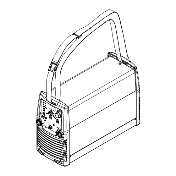
3-4. Selecting a Location Do not move or operate unit where it could tip. Shoulder Strap Use strap to lift unit. Movement Location And Airflow Special installation may be required where gasoline or volatile liquids are present − see NEC Article 511 or CEC Section 20. -
Page 17: Volt-Ampere Curves
Stick Max 10 20 30 40 90 100 110 120 130 140 150 160 170 180 190 DCAMPERAGE(A) STH 160 L Max Output − 160 A; STH 160 L Min Output − 4 A Stick TIG Max Stick/TIG Min Stick Max... -
Page 18: Duty Cycle And Overheating
NOTICE − Exceeding duty cycle can damage unit and void warranty. STH 160/ STH 160 L TIG STH 160 STICK STH 160 L STICK % DUTY CYCLE SECTION 4 − INSTALLATION 4-1. -
Page 19: Weld Output Terminals And Selecting Cable Sizes
4-2. Weld Output Terminals And Selecting Cable Sizes* NOTICE − The Total Cable Length in Weld Circuit (see table below) is the combined length of both weld cables. For example, if the power source is 30 m (100 ft) from the workpiece, the total cable length in the weld circuit is 60 m (2 cables x 30 m). Use the 60 m (200 ft) column to determine cable size. -
Page 20: Electrical Service Guide
In dedicated circuit installations, the National Electrical Code (NEC) allows the receptacle or conductor rating to be less than the rating of the circuit protection device. All components of the circuit must be physically compatible. See NEC articles 210.21, 630.11, and 630.12. STH 160 50/60 Hz 1 Phase STH 60L 50/60 Hz 1 Phase Input Voltage (V) -
Page 21: Connecting 1-Phase Input Power For 230 Vac
4-5. Connecting 1-Phase Input Power For 230 VAC =GND/PE Earth Ground Tools Needed: 956142809_1-6_B / 956142809_2-6_B OM-260311 Page 15... -
Page 22: Connecting To 1-Phase Engine Generator W/230 Volt Output
4-5. Connecting 1-Phase Input Power (Continued) Installation must meet all National and age available at site. Connect green or green/yellow grounding Local Codes − have only qualified per- conductor to disconnect device grounding Input Power Cord sons make this installation. terminal first. -
Page 23: Section 5 − Operation
SECTION 5 − OPERATION 5-1. Controls 8 8 8 Ref. 956142809_7-A Weld output terminals are energized Negative Weld Output Receptacle 10 Power Switch when power is On, and Ready Light is For Stick welding, connect work cable to this Place switch in On (I) position to turn unit on. lit. -
Page 24: Preparing Unit For Stick Welding
The amperage range while Stick with 15 percent being the default value. Voltage Reduction Setting The maximum Hot Start amperage value welding for the STH 160 L is from 4 To change voltage reduction setting, pro- is 150 amps. to 100 amps. -
Page 25: Preparing Unit For Tig Welding
5-3. Preparing Unit For TIG Welding =Light Flashing =Light Off =Light On =Light Flashing If Voltage Reduction Device Is On Process Selection Set-Up Menu Press And Release Press And Hold Positive Weld Output Terminal Prepare unit for TIG welding as follows: Press and release Amperage/Set-Up Adjustment control to select TIG welding Remote Control Receptacle... -
Page 26: Gas Connections (Sth Models)
5-4. Gas Connections (STH Models) Remove cap, stand to side of valve, and open valve slightly. Gas flow blows dust and dirt from valve. Close valve. Regulator/Flowmeter Install so face is vertical. Flow Adjust Typical flow rate is 15 CFH (cubic feet per hour) (7.1 liters per minute). -
Page 27: Or 4T Trigger Mode Settings
5-5. 2T Or 4T Trigger Mode Settings Process/Set-Up Selector Switch TIG HF Start TIG Lift Arc Start Light (LED) Ready Light (LED) Set-Up Light (LED) Ammeter And Parameter Display (Meter) Amperage/Set-Up Adjustment Control 2T and 4T are used with the TIG process. -
Page 28: Sequence Controls And Slope Down Settings
5-6. Sequence Controls And Slope Down Settings Sequencing is only available while using a TIG process. Select TIG process according to Section 5-3. Sequencer Control LEDs Ammeter And Parameter Display (Meter) Amperage/Set-Up Adjustment Control Sequencer Parameters Switch To enter Sequencer Control set-up mode and scroll through paramet- ers, press and release the Sequen- cer Parameters switch. -
Page 29: Pulser Control Settings
5-7. Pulser Control Settings Pulsing is only available while using a TIG process. Select TIG process according to Section 5-3. Pulser LEDs Ammeter And Parameter Display (Meter) Amperage/Set-Up Adjustment Control Pulser Control Switch Pulser Light (LED) Pulser light is on when pulser is on. To enter Pulser set-up mode and scroll through parameters, press and release the Pulser Control... -
Page 30: Resetting Unit To Factory Default Settings
5-8. Resetting Unit To Factory Default Settings This procedure will delete all operator specified parameters, and recall all factory parameters. Process/Set-up Switch Power Switch Press and hold the Process/Set-up switch and turn the power switch on. Hold the Process/Set-up switch until either 50A (TIG Mode) or 80A (MMA Mode) is dis- played. -
Page 31: Section 6 − Electrical Diagram
SECTION 6 − ELECTRICAL DIAGRAM 956142812-D Figure 6-1. Circuit Diagram For STH 160 And STH 160 L OM-260311 Page 25... -
Page 32: Section 7 − Parts List For Sth Models
... 057014276 Cable, Power w/Plug For STH 160 L ...... - Page 33 Dia. Part Mkgs. Description Quantity Figure 7-1. Main Assembly For STH 160 (Continued) ....208558 Term, Friction 250 x 0.32 .........
- Page 34 Notes MATERIAL THICKNESS GAUGE...
- Page 35 Effective January 1, 2018 (Equipment with a serial number preface of MJ or newer) This limited warranty supersedes all previous Miller warranties and is exclusive with no other guarantees or warranties expressed or implied. LIMITED WARRANTY − Subject to the terms and conditions 90 Days —...
- Page 36 File a claim for loss or damage during Phone: 39 (0) 2982901 Fax: 39 (0) 298290-203 shipment. email: miller@itw−welding.it For assistance in filing or settling claims, contact your distributor and/or equipment manufacturer’s Transportation Department. © ORIGINAL INSTRUCTIONS − PRINTED IN USA 2018 Miller Electric Mfg. LLC 2018−01...
Need help?
Do you have a question about the STH 160 and is the answer not in the manual?
Questions and answers