
Summary of Contents for JUMO variTRON 500
- Page 1 JUMO variTRON 500 Automation system PROFINET interface description 70500207T92Z001K000 V1.00/EN/00768869/2023-03-30...
-
Page 3: Table Of Contents
Device information ............25 Project integration of JUMO IO device into IO controller ......26 Error messages and status information . - Page 4 Contents...
-
Page 5: Introduction
Introduction 1 Introduction Warning symbols DANGER! This symbol indicates that personal injury from electrocution may occur if the appropriate precaution- ary measures are not taken. WARNING! This symbol in connection with the signal word indicates that personal injury may occur if the respective precautionary measures are not carried out. - Page 6 1 Introduction...
-
Page 7: Compatibility And System Requirements
Certification JUMO variTRON 500 The JUMO variTRON 500 automation system (product group 705002) is certified to Conformance Class A (abbreviated to CC-A) and net load class "Netload Class I." The certificate is available for download from the product page on the Internet. - Page 8 2 Compatibility and system requirements JUMO variTRON 500 To use PROFINET IO with the JUMO variTRON 500, the device must meet the following minimum re- quirements: • Device software version 388.7.1.0.4 • Hardware compatibility index (EM = electronic module): EM of CPU: 7050020301300001.01.01 EM of USB/Ethernet: 7050020000500001.01.01...
-
Page 9: Electrical Connection
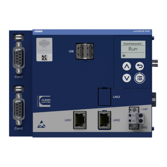
JUMO variTRON 500 Fig. 3-1 LAN interfaces of the JUMO variTRON 500 (LAN1 as a standard feature, LAN2 as an optional extra) LAN1 can be configured as a PROFINET IO device interface in CODESYS® (including Ethernet; extra code). - Page 10 3 Electrical connection...
-
Page 11: The Gsdml File
INET IO. Up to 19 modules are available for this purpose, which can be placed into slots 1 to 64. In con- trast to other JUMO IO devices, on the JUMO variTRON 500 no module is permanently integrated in a particular slot. -
Page 12: Modules
The configurable modules are intended exclusively for transferring cyclical IO items. The JUMO variTRON 500 supports up to 64 slots in total in the device and 64 slots in the IO controller project. The possible types of configurable modules are listed in the table below. - Page 13 4 The GSDML file Module designation Module types Data type Data direction (from the perspective of the IO IO controller controller) Input 8Bit Input values USINT8 (bit field) Read Output 8Bit Output values USINT8 (bit field) Write InOut 8Bit Input values USINT8 (bit field) Read Output values...
- Page 14 4 The GSDML file...
-
Page 15: Project Planning
Otherwise the transferred data will not be interpreted correctly! For JUMO field devices to be integrated into the project structure of the IO controller as an IO device, the GSDML file of the respective device must be imported into the engineering system of your IO con- troller. - Page 16 5 Project planning 6. The JUMO IO device uses the little endian format – please note this when configuring the IO con- troller and set it if required. 7. Insert the configured modules in the project structure of the IO controller in the desired slot position on the JUMO IO device.
-
Page 17: Configuring The Jumo Io Device
5 Project planning Configuring the JUMO IO device Using the JUMO variTRON 500 by way of example, this chapter explains how to integrate and configure a PROFINET IO device in CODESYS® using the setup program (JUMO smartWARE Setup variTRON) so that it can be found by an IO controller. This can then assign the IO device a device name and an IP address. -
Page 18: Configuration In Codesys® (Using The Setup Program)
This document does not cover how to start the setup program, create a project in the setup program, or start the CODESYS PLC programming system. These topics are covered in the operating manual for the JUMO variTRON 500 (705002). The operating manual can be downloaded from the relevant product page (705002) on the JUMO website (see chapter 2.1). - Page 19 5 Project planning 2. Create Ethernet interface.
- Page 20 5 Project planning 3. Configure network settings. The IP address must be identical to the IP address of the device created in the IO controller. Click Browse… to select the PROFINET interface (LAN port). Here, select the LAN1 interface that you previously configured manually (with the IP address 192.168.0.3 by way of example).
- Page 21 5 Project planning 5. Click Add Device to create an IO mapping of the PROFINET device (must be identical to the device in the IO controller). chapter 4.2.2 "Modules", Page 12...
- Page 22 5 Project planning 6. Map variables for IO mapping (receive 8 float values from controller). 7. Map variables for IO mapping (provide 1 float value for controller).
- Page 23 5 Project planning 8. Generate the code so that the application can be loaded into the JUMO variTRON 500 afterward. NOTE! The following steps 9 to 11 explain how to load an application into a CPU using CODESYS®. These steps are not required for configuration work using the setup program, but have nevertheless been in-...
- Page 24 LAN1 IP parameters are reset for PROFINET. In this case, perform a re- set on the JUMO variTRON 500 (power off/on) so that the application starts up and the PROFINET de- vice can be found by the IO controller.
-
Page 25: Device Information
The device info for the JUMO IO device displays, for inspection and error diagnostics, information about network configuration, hardware and software component versions, as well as counters for evaluating data traffic. For more details about the displayed data, see the operating manual for your JUMO IO de- vice. -
Page 26: Project Integration Of Jumo Io Device Into Io Controller
5 Project planning Project integration of JUMO IO device into IO controller Using the JUMO variTRON 500 by way of example, this chapter explains how to add the PROFINET IO device to an IO controller in CODESYS® and configure it. - Page 27 5 Project planning 2. Create Ethernet interface. NOTE! The exact procedure for integrating PROFINET IO devices can be found in the description of your engi- neering system.
- Page 28 5 Project planning 3. Configure network settings. Click Browse... to select the relevant interface. 4. Click Add Device to add the PROFINET controller to the Ethernet interface.
- Page 29 5. Configure the PROFINET controller. 6. Click "Add Device" to integrate the desired JUMO field device into the project structure of the IO con- troller. Make sure the device software version matches the version data of the JUMO field device integrated into the project structure.
- Page 30 The device will not connect to the IO controller without a valid IP configuration for the Ether- net interface. NOTE! The JUMO IO device is still accessible using the JUMO setup program or a web browser via Ethernet. The IP address of the Ethernet interface must be used for communication. Cyclical transfer timing: Send clock and reduction ratio determine the frequency at which an IO device transfers cyclical data in a PROFINET IO network.
- Page 31 The contents of the configurable modules can be determined by the user. In the engineering system, the modules must be assigned to the free slots in the JUMO IO device, so that they can be queried by the IO controller during the cyclical communication.
- Page 32 9. Map variables for IO mapping (send 8 float values to device). 10. Map variables for IO mapping (query 1 float value from device). The IO items of the JUMO IO device are now available for the programming of the IO controller.
- Page 33 5 Project planning 11. Connect to the PROFINET controller and click RUN to start the application.
- Page 34 5 Project planning...
-
Page 35: Error Messages And Status Information
As can be seen below, the configuration was successfully transferred to the device because the appli- cation has the status RUN and is ready for use. The JUMO IO device can now be found by an IO con- troller so that it can be assigned a device name and IP address. This is shown using the PRONETA tool from Siemens by way of example. -
Page 36: Status Information
NOTE! If the JUMO IO device is not found by the IO controller, the application in the IO device will not have the status RUN. In this case, switch the IO device off and back on. Following the restart, the application will then automatically switch to the status RUN. - Page 37 6 Error messages and status information Overview of PROFINET device statuses...
- Page 38 6 Error messages and status information...
- Page 40 JUMO GmbH & Co. KG JUMO Instrument Co. Ltd. JUMO Process Control, Inc. Street address: JUMO House 6724 Joy Road Moritz-Juchheim-Straße 1 Temple Bank, Riverway East Syracuse, NY 13057, USA 36039 Fulda, Germany Harlow, Essex, CM20 2DY, UK Delivery address:...
Need help?
Do you have a question about the variTRON 500 and is the answer not in the manual?
Questions and answers