Prokan BS04-BI-LP Assembly Instructions & User Manual
78" pro elite 4b european ledge island grill, pro elite 4b built-in grill, 30" double access drawers kit, 78" pro elite 4b golden white grill island, 60" pro elite 4b golden white q grill island
Hide thumbs
Also See for BS04-BI-LP:
- Assembly instructions & user manual (42 pages) ,
- Assembly instructions & user manual (44 pages)
Table of Contents
Advertisement
Assembly Instructions & User's Manual for
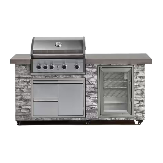
78" Pro Elite 4B European Ledge Island Grill
Item Number: K04000320A Model Number: BS04-BI-LP
Pro Elite 4B Built-in Grill
Item Number: K04000319A K04000345A Model Number: BS04R-BI-LP
30" Double access drawers kit Item Number: K01000321A
78" Pro Elite 4B Golden White Grill Island
Item Number: K04000342A Model Number: BS04RFIS-LP-A
60" Pro Elite 4B Golden White Q Grill Island
Item Number: K04000343A Model Number: BS04RCIS-LP-A
Customer Assistance
Email: support@1800acs.com/ contact@zhprokan.com
THIS ASSEMBLY MANUAL CONTAINS IMPORTANT SAFETY
INFORMATION. PLEASE READ AND KEEP FOR FUTURE REFERENCE.
DANGER
!
If you smell gas:
1.
Shut off gas to the appliance.
Extinguish any open flame.
2.
3.
Open lid.
If odor continues, keep away from
4.
the appliance and immediately call
your gas supplier or your fire
department.
(spare/replacement parts)
!
: 1-877-419-2598 or
WARNING
!
Do not store or use gasoline or other
1.
flammable liquids or vapors in the
vicinity of this or any other appli-
ances.
An LP cylinder not connected for
2.
use shall not be stored in the vicinity
of this or any other appliance.
Manual # PK000442021AE- Date: 2022/06
OPERATOR'S MANUAL
801480
!
1 |
P a g e
Advertisement
Table of Contents

Related Manuals for Prokan BS04-BI-LP


Summary of Contents for Prokan BS04-BI-LP
- Page 1 OPERATOR'S MANUAL Assembly Instructions & User’s Manual for 78" Pro Elite 4B European Ledge Island Grill Item Number: K04000320A Model Number: BS04-BI-LP Pro Elite 4B Built-in Grill Item Number: K04000319A K04000345A Model Number: BS04R-BI-LP 801480 30" Double access drawers kit Item Number: K01000321A 78"...
-
Page 2: Table Of Contents
Table of Contents Quality Statement ............................. 3 Important Safety Information ........................ 4 Natural Gas Safety Instructions......................5 Full System Features..........................6 Package Contents ............................7 Product Information ..........................8-9 Components .............................10 Tools ................................11 Assembly Instructions ..........................12-19 Part Diagrams and Lists ........................20-28 Warning ............................29 Danger ............................ -
Page 3: Quality Statement
Quality Statement Important Safety Information • Please read all instructions carefully before assembling this product. • Where applicable, and for your safety, assembly by an adult is strongly recommended. • Use only vendor-supplied hardware to assemble this item. Using unauthorized hardware could jeopardize the structural integrity of the item. -
Page 4: Important Safety Information
Important Safety Information PRE-ASSEMBLY CAUTION Read and perform the following pre-assembly instruc- tions: Tools Required for Assembly Failure to comply with these instructions may result in a hazardous situation which, if not avoided, may • protective work gloves result in injury. •... -
Page 5: Natural Gas Safety Instructions
Natural Gas Safety Instructions • Your Natural Gas BBQ is designed to operate on • WARNING: Do not route the 10 foot Quick Natural Gas only, at a pressure of 7" water column Disconnect Hose under a deck. The hose must (W.C.) (1/4 psig or 1.75 kpa), regulated at the be visible and inspected prior to each grill use. -
Page 6: Full System Features
Full System Features-BS04-BI-LP/BS04RFIS-LP-A Sold Separately Description Component Part# Full Rust-Proof Cast Main Burner:40,000 BTU Weather Aluminum Firebox Rear Burner:12.000 BTU Resistant Countertop Grill Topper KPSS005 KPSS004 Charcoal Insert Self-Leveling S0221-13 63L Fridge Adjustable Legs Double Access Propane Tank Caster for Easy... -
Page 7: Package Contents
Package Contents Y0250200BP Rotisserie Assembly Parts Diagram IMPORTANT: Please note that the rotisserie rod is packed on the back of the grill box. Y0250200BP Rotisserie Assembly Parts List Component Description Quantity PAR T# P05508200A Rot. Collar Rot. Thumbscrew 1/4"x1/2" S196G04081 Rot. -
Page 8: Product Information
Product Information 78.3" 33.17" BS04-BI-LP BS04RFIS-LP-A 60.5" 605" 26.95" 30.94" BS04RCIS-LP-A P a g e... - Page 9 Product Information 31.9" 25" 30.2" 21.14" P a g e...
-
Page 10: Components
Components Components Cooking Grid Warming Rack lame amer No.S0224-08 No.S0224-09 No.S0224-06 Qty 2 Qty 1 Qty 4 Fridge No.S0226-05 Qty 1 P a g e... -
Page 11: Tools
Tools Phillips Screwdriver (Not Caster Wrench Included) P a g e... -
Page 12: Assembly Instructions
ASSEMBLY BS04-BI-LP/BS04RFIS-LP-A CAUTION : To assemble this grill, you should obtain assistance from another person when handling some of the larger, heavier pieces. Step 1: Connect regulator to propane tank. P a g e... - Page 13 Step 2: Adjustable Level are located underside of the Island Assembly as shown. If the Island sets are not level with each others, adjust the 6 preassembled Adjustable Level using the wrench provided. - Turn the adjusters clockwise to raise the height of the Island. - Turn the adjusters counterclockwise to lower the Island.
- Page 14 Step 4: Install Cooking Components Place the Flame Tamers above the Burners. Cooking Rack Place the Cooking Grids on the ledge Part No.S0224-09 Qty 1 above the Flame Tamer. Place the Secondary Cooking Rack onto the Warming rack holder. Cooking Rack Part No.S0224-08 Final Grill Assembly Step Qty 2...
- Page 15 Step 5 1. Remove all components from the carton. Attach the Motor Bracket on the outside of the left grill bowl panel. Align the two holes of the Bracket with the holes on the grill bowl panel. Tighten securely using two Screws #10-24x1" UNC and Nuts provided.(Fig. 1) Attach the Collar Support Bracket with a threaded screw over the middle hole on the right grill bowl panel.
- Page 16 Step 6 Install the AC (alternating current) Rotisserie Motor onto the Motor Bracket as shown below. Be sure the Motor attaches to the Bracket with the electrical cord down. Rotisserie Motor Step 7 Insert the assembled Rotisserie into the Motor as shown below. The Motor should be on the left side of your grill. Place the Collar into the slot opening on collar support bracket, then tighten the Collar Thumbscrew on the left end of Collar.
- Page 17 ASSEMBLY BS04R-BI-LP Step 1: Install the Trim brackets . Phillips Head Screw 1/4" 3/8" Qty. 4 Step 2: Install the grill onto the housing. 17 | P a g e...
- Page 18 Step 3: Ignition Battery. 18 | P a g e...
- Page 19 Step 4: Cooking Component Installation. Warming Rack Cooking Grid Flame Tamer 19 | P a g e...
-
Page 20: Part Diagrams And Lists
Part Diagrams and Lists-BS04R-BI-LP 20 | P a g e... - Page 21 Part Diagrams and Lists-BS04R-BI-LP DESCRIPTION PART# Protective Pad,Rear S0128-35 Protective Pad,Front 111-160 Temperature Gauge S0209-16 Thermometer Bezel S0202-19 26-01 Lid Assembly Cast Aluminum Grill Box 24-01 Control Panel,Upper 26-02 S0224-03 Control Panel,Lower Gas Valve Heat Shield Panel S0224-04 Control panel end cap, Left 224-05A Control panel end cap, Right 224-05B...
- Page 22 Appendix Page for Pro Elite 4B Built-in Grill (Item Number: K04000345A;Model Number: BS04R-BI-LP) DESCRIPTION PART# COMPONENTS Cast Iron Cooking Grid for Pro Elite S0225-01 Cast Iron Hotplate for Pro Elite S0225-02 22 | P a g e...
- Page 23 Part Diagrams and Lists-BS04RCIS-LP-A For Natural Gas Model Only Natural Gas Conversion Kit Sold Separately (Manufacturer part #: KPSS002). Self-Leveling adjustable legs: Sold separately. (Manufacturer part #: S0221-13). 23 | P a g e...
- Page 24 Part Diagrams and Lists-BS04RCIS-LP-A DESCRIPTION PART# Protective Pad,Rear 111-160 Protective Pad,Front 111-160 Temperature Gauge S0209-16 Thermometer Bezel 0202-19 07-01Z Lid Assembly Cast Aluminum Grill Box 24-01 Control Panel,Upper 26-02 S0224-03 Control Panel,Lower Gas Valve Heat Shield Panel S0224-04 Control panel end cap, Left 224-05A Control panel end cap, Right 224-05B...
- Page 25 Part Diagrams and Lists-BS04-BI-LP/BS04RFIS-LP-A Self-Leveling adjustable legs: Sold separately. (Manufacturer part #: S0221-13). For Natural Gas Model Only Natural Gas Conversion Kit Sold Separately (Manufacturer part #: KPSS002) 25 | P a g e...
- Page 26 Part Diagrams and Lists-BS04-BI-LP/BS04RFIS-LP-A DESCRIPTION PART# Protective Pad,Rear S0111-160 Protective Pad,Front 111-160 Temperature Gauge S0209-16 Thermometer Bezel 0202-19 26-01 Lid Assembly Cast Aluminum Grill Box 24-01 Control Panel,Upper 26-02 Control Panel,Lower S0224-03 Gas Valve Heat Shield Panel S0224-04 Control panel end cap, Left...
- Page 27 Part Diagrams and Lists-BS04-BI-LP/BS04RFIS-LP-A PART# DESCRIPTION 224-23 Door Trim Plate Door Trim Plate S0224-27 S0224-28 Door, Tank Storage Drawer Assembly S0224-34Z Drawer Slide set 05-45 2 set Countertop, Left S0224-52 (for BS04-BI-LP) Countertop, Left S0226-09 (for BS04RFIS-LP-A) Countertop, Rear S0224-53...
- Page 28 Part Diagrams and Lists-Drawer Set PART# DESCRIPTION Door Trim Frame S0224-27 Door, Tank Storage 224-28 Drawer Assembly 224-34Z 2 set Drawer Slide set 05-45 30" 14.2" 30" 19.2" 28 | P a g e...
-
Page 29: Warning
WARNING WARNING WARNING • This appliance, when installed, must be electri- cally grounded in accordance with local codes • LPG models must be used with Liquid Propane or, in the absence of local codes, with the Gas and the regulator assembly supplied. Natural National Electrical Code, ANSI/NFPA 70, or the Gas models must be used with Natural Gas only. -
Page 30: Danger
Danger DANGER Do not use an open flame to check for gas leaks. Be sure there are no sparks or open flames in the area while you check for gas leaks. This will result in a fire or explosion which can cause serious bodily injury or death, and damage to property. -
Page 31: Troubleshooting
Troubleshooting Troubleshooting To purge air from your gas line and/or reset If the grill fails to light : the regulator excess gas flow device: Turn gas off at source and turn Control Knobs to OFF. Wait Turn Control Knobs to the OFF position. at least 5 minutes for gas to clear, then retry. - Page 32 Troubleshooting Answer: Question: The humming sound is gas flowing through the regulator. Can I convert my grill from LPG to NG? A low volume of sound is normal and will not interfere with the operation of your grill. Loud or excessive regulator Answer: humming and/or low flow and intermittent lighting may No, your gas grill is manufactured to exact specifications and is...
- Page 33 Troubleshooting Question: After every use (after your grill has cooled down), wipe The Regulator and Hose supplied with my gas grill stainless surfaces with a soft, soapy cloth or sponge does not fit the older LP Gas tank I’ve used for years. then rinse with water.
-
Page 34: Care & Use Instructions
Care & Use Instructions CORRECT LP GAS TANK USE Keep fire extinguisher readily accessible. In the event LP Gas grill models are designed for use with a standard of a oil/grease fire, do not attempt to extinguish with 20 lb. Liquid Propane Gas (LP Gas) tank (sold sepa- water. - Page 35 Care & Use Instructions LP Gas Model only: NOTE about LP Gas Tank Exchange Programs To Secure a 20lb LP Gas Tank to the tank Many retailers who sell grills offer you the option of re- storage placing your empty LP Gas tank through an exchange service.
- Page 36 Care & Use Instructions LP Gas Model only: Check all connections for LP Gas Leaks Connect Regulator with Hose to your LP Gas Tank Never test for leaks with an open flame. Prior to first use, at the beginning of each season, or every time Turn all Burner Valves to the OFF position.
- Page 37 Care & Use Instructions Main Burner Lighting Instructions Repeat steps to light each burner individually. Note: When Before each use, check all hoses for cracks, nicks, cuts, burns or abrasions. If a hose is damaged in any way, do lighting all main burners, start with the burner furthest from fuel source location, then light remaining burners in se- not use your grill before replacing the hose with an quence moving toward fuel source.
- Page 38 Care & Use Instructions Cleaning Exterior Stainless Steel Surfaces: Proper care and maintenance will keep your grill in top operating condition and prolong its life. Follow these cleaning procedures Routine care and maintenance is required to preserve on a timely basis and your grill will stay clean and operate with the appearance and corrosion resistance of stainless minimum effort.
- Page 39 Care & Use Instructions Manually Lighting Your Grill By Paper Match CAUTION To light your gas grill by match, insert a match into the Lighting Stick and follow steps 1 through 5 of the Grill Lighting Instructions. Then, light the match and place Never lean over the grill cooking area while lighting Lighting Stick through the Cooking Grids on the grill (See your gas grill.
- Page 40 Care & Use Instructions CORRECT ROTISSERIE USE ELECTRICAL EQUIPMENT USE Read all instructions before initial use. To protect against electric shock, do not immerse cord or IMPORTANT: When using electrical appliances, basic safety plugs in water or other liquid. precautions should always be used. The Rotisserie Motor is set for 120V, 60Hz AC current.
- Page 41 Care & Use Instructions Cleaning the burner tubes and burner ports. To reduce the chance of FLASHBACK FIRE you must clean Regardless of which Burner cleaning procedure you use, we recommend that you also complete the follow- the Burner Tubes as follows at least once a month in summer and fall or whenever spiders are active in your ing cleaning regimens to help prolong Burner life.
-
Page 42: Storage Instructions
2. Disconnect the tank and store it in an upright position in an outdoor space away from dryer and furnace vents and play areas. Item BS04-BI-LP 3. Coat the burners and other metal parts with cooking oil to repel moisture BS04R-BI-LP that can build up over the winter and to prevent rust. -
Page 43: Technical Data
Technical Data SPECIFICATIONS Models/Finish BS04R-BI-LP/ BS04-BI-LP/BS04RFIS-LP-A Main Burners 4x10,000 BTU/HR Rotisserie Burner 12,000 BTU/HR 30.2 × 25×20.01 in. (BS04R-BI-LP) Dimensions (L × W × H) 78.3× 33.17 ×47.92 in. (BS04-BI-LP/ BS04RFIS-LP-A) Warranty 1-year limited Models/Finish BS04RCIS-LP-A Main Burners 4x10,000 BTU/HR... -
Page 44: Warranty Information
Warranty Information Should you encounter any problem, Please contact us first. DON’T Return the product to the store. We can help. For assistance, contact customer service at support@1800acs.com / contact@zhprokan.com or call 1-877-419-2598 Monday through Friday from 8:00 a.m. to 8:00 p.m. EST. Please note that the limited warranty is given to and covers the Original purchaser only and such coverage is not transferable. - Page 45 onta t Information 45 | P a g e...
Need help?
Do you have a question about the BS04-BI-LP and is the answer not in the manual?
Questions and answers