Table of Contents
Advertisement
Quick Links
Advertisement
Table of Contents

Related Manuals for HANYOUNG NUX MC9 Series


Summary of Contents for HANYOUNG NUX MC9 Series
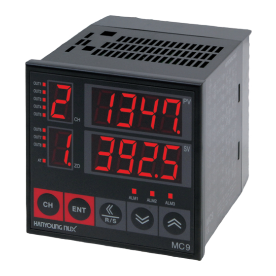
- Page 1 Multi Channel Temperature Controller operation manual Thank you very much for purchasing Hanyoung Nux products. Please use the product according to the intended use after reading the operation manual to see if it is the product you want. Also, be sure to keep this manual.
-
Page 3: Table Of Contents
Before Start 01. Warranty policy 02. Safety Precautions Install 2.1 Installation location and precautions 2.2 Input type & Range Code 2.3 Appearance and panel processing dimensions 2.4 Connection diagram 2.5 Communication connection example How to set 3.1 Name of each part 3.2 Parameter diagram 3.3 Parameter setting range and initial setting value 3.4 Measured value (PV) / set value (SV) display mode... -
Page 4: Warranty Policy
Warranty policy The standard warranty period for new products is 1 year(12 months), Hanyoungnux will repair free of charge only in the case of a failure that occurs under normal use as specified in this operation manual. Except as stipulated in our warranty terms, we do not accept any warranty or responsibility for this product. -
Page 5: Safety Precautions
▍ Safety Precautions BEFORE using this device, read this manual and save for future reference. Signal words are used in this manual and apply to hazards or unsafe practices which could result in injury or property damage See the information below for definitions of the signal words. Danger indicates an imminently hazardous situation which, if not avoided, Danger will result in death or serious injury. -
Page 6: Installation Location And Precautions
▍ Installation ■ Installation location and precautions ▪Installation place Danger As there is a risk of electric shock, use this product while it is installed on the panel. • Do not install in the following places. - Where a person may unknowingly come into contact with the terminal. - Where directly exposed to mechanical vibrations or shocks. - Page 7 ▍ Model configuration ■ 4 Channels Model Code Description MC9-4 ⃞ ⃞ ⃞ ⃞ ⃞ 4Channel Digital Thermostat size : 96 (W) X 96 (H) ㎜ Cooling control (direct action) Control type Heating control (reverse action) Input type ⃞ Refre to "code" of input code chart Relay contact output Output 1 ~ 4 SSR operation output...
-
Page 8: Input Type & Range Code
▍ Input type & Range code Category Code Input Type Input Range (℃) Accuracy -200 ~ 1,370 -199.9 ~ 999.9 -200 ~ 1200 -199.9 ~ 999.9 -200 ~ 900 -199.9 ~ 900.0 -199.9 ~ 400.0 0 ~ 1700 0.0 ~ 999.9 ±... -
Page 9: Connection Diagram
▍ Dimentions & Panel cutout [Unit:mm] ▪External dimensions ▪Panel cutout 100.0 96.0 91.5 74.0 26.0 120.0 9 9 9... - Page 10 ▍ Connection diagrams Output 1 ~ 4 Output 5 ~ 8 ■ ■ Power input 100 - 240 V a.c. Alarm 2output Alarm 1 output Alarm 3output Output 5 Output 1 Relay SSR/Current output Relay SSR/Current output Output 6 Output 2 Relay SSR/Current output Relay...
- Page 11 Input (1) 1 ~ 4 Channels Input (2) 5 ~ 8 Channels ■ ■ Channels 1 Channels 5 V d.c. V d.c. Channels 2 Channels 6 V d.c. V d.c. Channels 3 Channels 7 V d.c. V d.c. Channels 4 Channels 8 V d.c.
-
Page 12: Communication Connection Example
▍ Communication connection example RS422 / RS485 ■ Up to 32 units can be connected. Be sure to connect a terminating resistor (100 Ω ~ 200 Ω 1/4 W) at both ends of the communication path. ▪2-wire Terminating Resistance Terminating Resistance Terminating Resistance... -
Page 13: How To Set
▍ How to set ■ Name & Function ① : Channel number display ① ② : Control output and Auto-tuning display ③ : Memory zone indication ② ⑪ ④ : Channel change (CH) ⑤ : Enter (ENT) ⑥ : Shif ⑩... -
Page 14: Parameter Diagram
█ Parameter diagram ① ① ① ① ② ⑪ ② ⑪ Power on (input type and range display) ② ⑪ ⑩ ⑩ ② ⑪ ③ ③ ⑨ ⑨ ⑩ ⑩ ③ ③ ④ ④ ⑧ ⑧ ⑨ ⑨ ⑤ ⑥ ⑦ ⑤ ⑥... -
Page 15: Parameter Setting Range And Initial Setting Value
■ Parameter setting range & Initial setting value ■ PV/SV Display mode & SV setting & Display mode Signal Name Range Initial Value Unit Memory zone Channel Temperature Within range setpoint Memory zone 1 ~ 8 Absolute value ■ General setting mode Signal Name Range Initial Value Unit Memory zone Channel OFF. 0.1 ~ 200.0 Loop break alarm Minute minute Loop break... - Page 16 ■ Initial setting mode Signal Name Range Initial Value Unit Memory zone Channel Auto tuning OFF, ON (A.T) Temperature 0.0 ~ 100 % compensation FR-L ~ Input range Upper limit range upper limit range upper limit upper limit range Input range lower limit range ~ FR-H lower limit Alarm-1 type...
-
Page 17: Measured Value (Pv) / Set Value (Sv) Display Mode
■ Measured value / Set value display mode In the measured value (PV) / set value (SV) display mode, it is a screen to check the measured value (PV) and set value ① (SV) corresponding to the channel number displayed on the channel (CH) window. ②... -
Page 18: Normal Setting Mode
② ⑪ ① ① ① ■ General setting mode ⑩ ③ 91.5 +0.8-0 ② ⑪ ② ② ⑪ ⑪ ⑨ Press the key for 2 seconds on the display screen to enter the "General setting mode" ④ ⑧ In this setting mode, it is a parameter setting mode in which the user frequently changes the setting value, and it can ⑩... - Page 19 █ Alarm-3 setpoint (AL 3) •Initial value : Maximum value of range (refer to input type and range code table) 셋업모드 •Setting range : Range (refer to input type and range code table) 셋업모드 •Description : Please set the set value of alarm 3 셋업모드...
- Page 20 █ Set value change rate limit (RATE) •Initial value : OFF •Setting range : 0(0.0) ~ Range maximun / minute •Description : Set the target value (SV) change per minute. If set to OFF, it does not work. If the target value (SV) is changed during operation (RUN), the slope setting (RATE) is activated.
-
Page 21: Initial Setting Mode
② ⑪ ② ⑪ ① ① ① ■ Initial setting mode ⑩ ⑩ ③ ③ ② ② ⑪ ⑪ ② ⑪ ⑨ ⑨ In display mode or general setting mode, press keys at the same time to enter "initial setting mode". ④ ④ ⑧... - Page 22 █ Alarm-1 type (ALT 1) •Initial value : 0 •Setting range : 0 ~ 16 •Description : Set the type of alarm 1. Please refer to 5-3 Alarm Action. █ Alarm-2 type (ALT 2) •Initial value : 0 •Setting range : 0 ~ 16 •Description : Set the type of alarm 2.
- Page 23 █ Communication address (ADD) •Initial value : 1 •Setting range : 1 ~ 99 •Description : Select the communication function option and the parameters will be displayed. For RS422/485 communication, the address of the device is stored. For details, refer to the communication manual. █ Select communication protocol (PSL) •Initial value : 0 •Setting range : 0 ~ 1...
- Page 24 █ Data length (DLN) •Initial value : 7 •Setting range : 7 ~ 8 •Contents : ·Set the communication data length. ·Select the communication option and the parameters will be displayed. 7 : 7 BIT 8 : 8 BIT █ Response time (RPT) •Initial value : 0 •Setting range : 0 ~ 10 •Contents : ·Set the communication response time.
-
Page 25: Setting Sequence
█ Setting sequence ① █ Settings by channel ② ⑪ An example of changing the temperature set value (SV) is as follows. The same setting method applies to other parameters not described here. ⑩ ③ ⑨ ① █ How to change the temperature set value (SV) ④ ⑧ ② ⑪ “Follow the procedure below to change the “Channel 1” setting of “Memory Zone 1” from -199.9 ℃ to 300.0 ℃. ⑤... - Page 26 ① ② ⑪ █ When setting value (SV) increases (when changing from 400 to 390) ② ⑪ ⑩ ③ ⑨ ⑩ • As shown in the picture below, press the key twice to flash the ten digit number. ③ 91.5 +0.8-0.0 ⑧ ④ ⑨ • Press the key once to change the 10th "0" to a "9". ⑧...
- Page 27 ① ② ⑪ ① ⑩ ③ ① ⑨ 2. Each time press the key to change from one 1 to zone 2, ② ⑪ ④ ⑧ the digits of the SV (setpoint) appear sequentially as shown ② ⑪ below, and "1" flashes when the cursor is on the number "1". ⑩...
- Page 28 █ When setting all set values (SV) at once When to set the channel setting value (SV) of 1-8 corresponding to Zone “1” from 0 ℃ to 200 ℃ all at once 1. • If the ENT key is pressed in the PV/SV display state, the screen on as the left is displayed •...
-
Page 29: Set Value (Sv) Change
▍ Operation ① ② ⑪ This chapter describes the machine's operation, operation/stop switching, and memory area. When the power voltage is applied after the wiring is completed, the operation starts after about 3 seconds. ⑩ ③ ⑨ (However, the operation stops according to the initial value setting. Press the key to start RUN.) ④... -
Page 30: Control Memory Zone Change
② ⑪ █ Operation/Stop selection by external contact input (D.I) (option) ⑩ ③ ⑨ First, select “1 (Use D.I)” for the function mode “D.I selection” parameter, and then press the front in the operation screen (display current temperature). ④ ⑧ ① Press to turn on the external contact input (No. 37-38) when “ ”... -
Page 31: Auto Tuning
█ Auto tuning (Autotuning) The auto-tuning function automatically calculates and calculates the optimal PID value and LBA setting time, and sets the values to each parameter. █ Auto tuning execution Auto-tuning is executed when all of the following conditions are satisfied. 1) Set all parameters except PID(PB,TI,TD) and LBA. 2) In setup mode, lock level 1 (LOCK1) and lock level (LOCK2) are set to “0000”. - Page 32 █ Input correction function (Bias) The measured value is corrected by adding the value set in the input correction (Bias) parameter to the value input by the sensor. Deviation █ Digital filter function (Filter) In order to reduce the fluctuation of the measured value (PV) due to noise, the influence of input noise can be suppressed by appropriately setting the time constant of the filter according to the noise level.
- Page 33 █ Alarm function • Alarm output is commonly applied to all channels. That is, if any one of 4 channels or 8 channels satisfies the alarm output conditions, the alarm output operates. • Hysteresis for alarm output is set to 2 ℃ (2 %). •...
- Page 34 High temperatur ALARM AREA ALARM AREA P-BAND temperature temperature temperatur High High High • Example of alarm operation (▲ : Control error setting value, △ : Alarm temperature setpoint) temperature temperature temperature temperature temperature temperature Alarm type Alarm operation High High temperature temperature...
- Page 35 Alarm type Alarm operation Deviation There is a Deviation standby operation There is no Deviation standby operation. Deviation █ Control loop break alarm (LBA) If the measured value (PV) is within the proportional band (PB), After Before change change the LBA operation is not performed and LBA operation starts after it is out of the proportional band. Decrease the set ...
-
Page 36: Error Message
ERROR DISPLAYS (TROUBLESHOOTING) █ Display Meaning PV window display Action & status of control When the measured OVR : Display current Countermeasure : Check PV value value (PV) exceeds PV value alternately Output state: Normal operation the input range up to EU (105 %) PV status: Normal operation -OVR : Display current PV value alternately... -
Page 37: Specification
Specification ▍ Input specifications █ Title Description Thermocouple (T.C) : K, J, R, S, B, E, N, T, W, PL2, U, L Temperature input RTD (R.T.D) : Pt100 Ω, KPt100 Ω (multi input) Direct current voltage (DCV) : 0 ~ 5 V, 1 ~ 5 V, 0 ~ 10 V,4 ~ 20 ㎃ (250 Ω... -
Page 38: General Specifications
General specification █ Title Description Power supply voltage 100 - 240 V a.c., 60 ㎐ Voltage fluctuation rate Power supply voltage ±10 % Power consumption 21 VA Ambient temperature 0 - 50 ℃ Ambient humidity 35 - 85 % RH (Without condensation) Storage temperature -25 ~ 65 ℃... -
Page 39: Frequently Asked Questions(Faq)
▍ Frequently Asked Questions(FAQ) Questions & Answers Q : "KSTP" is displayed on the temperature display window, the device does not work. A : When this KEY is pressed for 3 seconds, the stop status is released and the operation state is performed. - Page 40 Q : I want to set the setting value to the same value for 8 channels at the same time, how to do? A : To set the same value for eight channels, The parameter is set to A then input, will be set to the same value for eight channels. Q : Is it possible to auto-tune at 8 channels once? A : If you press ENT+<<...
- Page 45 MA0401E220517_U 28, Gilpa-ro 71beon-gil, Michuhol-gu, Incheon, korea Tell : +82-32-876-4697 E-mail : ovterseas@hynux.com http://www.hanyoungnux.com...
Need help?
Do you have a question about the MC9 Series and is the answer not in the manual?
Questions and answers