Table of Contents
Advertisement
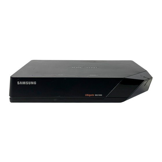
Quick Links
Advertisement
Table of Contents

Related Manuals for Samsung Ubigate iBG1000


Summary of Contents for Samsung Ubigate iBG1000
- Page 2 COPYRIGHT This manual is proprietary to SAMSUNG Electronics Co., Ltd. and is protected by copyright. No information contained herein may be copied, translated, transcribed or duplicated for any commercial purposes or disclosed to third parties in any form without the prior written consent of SAMSUNG Electronics Co., Ltd.
-
Page 3: General User Information
FCC REQUIREMENTS This equipment, the Ubigate iBG1000, complies with Part 68 of the FCC rules and the requirements adopted by the ATCA. On the bottom of this equipment is a label that contains, among other information, a product identifier in the format US: A3LIS00BiBG1000. - Page 4 If requested, this information must be provided to your telephone company. INCIDENCE OF HARM If this equipment, the Ubigate iBG1000, causes harm to the telephone network, the telephone company will notify you in advance that temporary discontinuance of service may be required. But if advance notice isn’t practical, the telephone company will notify the customer as soon as possible.
- Page 5 Ubigate iBG1000 Installation Manual/Ed.02 SERVICE CENTER If trouble is experienced with the Ubigate iBG1000, please contact your local office of SAMSUNG ELECTRONICS, CO., LTD. for repair or warranty information. If the trouble is causing harm to the telephone network, the telephone company may request that you remove the equipment from the network until the problem is resolved.
-
Page 6: Safety Warning
Every wire for communication should be larger than 26 AWG. Double pole/neutral fusing. UNDERWRITERS LABORATORIES The Ubigate iBG1000 system has been tested to comply with safety standards in the United States and Canada. This system is listed with Underwriters Laboratories. The cUL Mark is separately shown on the label. - Page 7 Ubigate iBG1000 Installation Manual/Ed.02 Warning to service personnel: CAUTION: Double pole/neutral fusing Telephone line cord: CAUTION: To reduce the risk of fire, use only No. 26 AWG or larger (e.g., 24 AWG) UL Listed or CSA Certified Telecommunication Line Cord Leakage currents due to ringing voltage - Earthing installation instructions: 1.
- Page 8 E) Reliable Earthing - Reliable earthing of rack-mounted equipment should be maintained. Particular attention should be given to supply connections other than direct connections to the branch circuit (e.g., use of power strips).’ © SAMSUNG Electronics Co., Ltd.
-
Page 9: Introduction
Ubigate iBG1000 Installation Manual INTRODUCTION Purpose Ubigate iBG1000™ Installation Manual provides instructions on installing the Ubigate iBG1000, including hardware descriptions, safety information, chassis installation, module installation, interconnection, and troubleshooting descriptions. Document Content and Organization This manual is composed of three Chapters and two Annexes. -
Page 10: Conventions
Information for Product and Technical Support For questions regarding the product and technical supports: http://www.samsungnetwork.com Revision History EDITION DATE OF ISSUE REMARKS 05. 2008. First edition 06. 2008. Added caution for power adapter 10. 2008. Modified tabletop installation VIII © SAMSUNG Electronics Co., Ltd. -
Page 11: Safety Concerns
Ubigate iBG1000 Installation Manual SAFETY CONCERNS The purpose of the Safety Concerns section is to ensure the safety of users and prevent property damage. Please read this document carefully for proper use. Symbols Caution Indication of a general caution. Restriction Indication for prohibiting an action for a product. -
Page 12: Warning
Do not place any items that weigh more than 10 pounds (4.5 kilograms) on top of the chassis, and do not stack routers on a tabletop. Use only the adapter provided with the Ubigate iBG1000. Using other adapter can result in overheating or explosion and may cause malfunction. -
Page 13: Table Of Contents
Symbols ........................IX Warning........................X Caution........................X CHAPTER 1. Ubigate iBG1000 Overview Ubigate iBG1000 Chassis ................... 1-1 Ubigate iBG1000 Top Side ..................1-2 Ubigate iBG1000 Rear Side ................... 1-3 Ubigate iBG1000 Hardware ..................1-4 Memory ......................... 1-4 Power Supply ......................1-4 Ventilation......................1-5 Real-Time Clock .................... - Page 14 Connecting the Ubigate iBG1000................3-7 LAN Interface......................3-7 T1/E1 Interface ...................... 3-8 Console Interface....................3-9 Auxiliary Interface (for Remote Access)..............3-10 Powering Up the Ubigate iBG1000................3-12 Connecting Power....................3-12 Applying Power....................3-13 ANNEX A. Specifications Ubigate iBG1000 Product Specifications..............A-1 Interface........................
- Page 15 Ubigate iBG1000 Installation Manual/Ed.02 Ethernet LAN Interface...................A-3 ANNEX B. Cable Specifications Console Port Cable .....................B-1 Auxiliary Port Cable ....................B-2 Ethernet Cable ......................B-3 T1/E1 Cable .........................B-4 XIII © SAMSUNG Electronics Co., Ltd.
- Page 16 Figure 1.2 Ubigate iBG1000 Rear Connector............1-3 Figure 1.3 Power Supply..................1-4 Figure 1.4 Ventilation ................... 1-5 Figure 2.1 Air flow of the Ubigate iBG1000 ............2-3 Figure 3.1 Making holes..................3-2 Figure 3.2 Insert plastic anchors................3-3 Figure 3.3 Tightening screws ................3-3 Figure 3.4 Fixing on a wall ...................
-
Page 17: Chapter 1. Ubigate Ibg1000 Overview
CHAPTER 1. Ubigate iBG1000 Overview Chapter 1 provides an overview of the Ubigate iBG1000. This chapter provides an overview of Ubigate iBG1000 including information about chassis components and hardware characteristics. Ubigate iBG1000 Chassis This section describes chassis components of the Ubigate iBG1000. -
Page 18: Ubigate Ibg1000 Top Side
CHAPTER 1. Ubigate iBG1000 Overview Ubigate iBG1000 Top Side The top side of Ubigate iBG1000 has LEDs in order to indicate the router’s performance and operation status. Each LED’s description is shown as follows. T1/E1 Ethernet Figure 1.1 Ubigate iBG1000 Top View LED Description Indication &... -
Page 19: Ubigate Ibg1000 Rear Side
Power supply installed but power fault condition detected. Power supply not present or power supply failure Ubigate iBG1000 Rear Side Ubigate iBG1000 rear side has four T1/E1 ports, two Fast Ethernet UTP ports, one auxiliary port, and one console port. Console Port Auxiliary Port... -
Page 20: Ubigate Ibg1000 Hardware
Internal Flash Memory: Ubigate iBG1000 includes 2 MB of internal flash Ÿ memory which is used to boot the router. Power Supply Ubigate iBG1000’s AC power adapter provides +12 VDC with an AC input between 100 and 240 VAC. Figure 1.3 Power Supply © SAMSUNG Electronics Co., Ltd. -
Page 21: Ventilation
Ubigate iBG1000 Installation Manual/Ed.02 Ventilation On both sides, there are grids of holes where air comes in and goes out. When installing Ubigate iBG1000, ensure to make room around the system in order not to block air flow. Figure 1.4 Ventilation... - Page 22 CHAPTER 1. Ubigate iBG1000 Overview This page is intentionally left blank. © SAMSUNG Electronics Co., Ltd.
-
Page 23: Chapter 2. Pre-Installation Requirements
CHAPTER 2. Pre-Installation Requirements Chapter 2 describes how to prepare for installing an Ubigate iBG1000. This chapter describes how to prepare for an Ubigate iBG1000. Before you install an Ubigate iBG1000, familiarize yourself with the network interface, power, and ground connections described in the following paragraphs. -
Page 24: Cover Panels
CHAPTER 2. Pre-Installation Requirements Cover Panels Do not operate the Ubigate iBG1000 with missing cover panel. The cover prevents exposure to hazardous voltages and currents inside the chassis. It is important to maintaining proper air flow through the chassis. It also prevents electromagnetic interference (EMI) that might disrupt other equipment. -
Page 25: General Site Requirements
For safety, Ubigate iBG1000 is intended to be installed in a restricted access location by a service person. See Required Tools and Materials for information about tools and materials required for installation. -
Page 26: Inspecting The Ubigate Ibg1000
Plastic anchor and screw 2 sets Ÿ Quick Start Guide Ÿ Manual CD Ÿ Inspect the Ubigate iBG1000 for damage that may have occurred during shipping. If you discover damage or missing items, contact Technical Support: http://www.samsungnetwork.com © SAMSUNG Electronics Co., Ltd. -
Page 27: Required Tools And Materials
Ubigate iBG1000 Installation Manual/Ed.02 Required Tools and Materials The following additional items may be required to install these routers in your operating environment. This is dependent on router configuration and how the router will be managed. Tools The following tools are required to install these routers. - Page 28 CHAPTER 2. Pre-Installation Requirements This page is intentionally left blank. © SAMSUNG Electronics Co., Ltd.
-
Page 29: Chapter 3. Ubigate Ibg1000 Installation
CHAPTER 3. Ubigate iBG1000 Installation Chapter 3 describes how to install Ubigate iBG1000 for operation in a network facility. Installing the Ubigate iBG1000 This section describes how to prepare the Ubigate iBG1000 for operation either as a tabletop or a wall-mounted unit. -
Page 30: Installing On A Wall
CHAPTER 3. Ubigate iBG1000 Installation Installing on a Wall This section describes how to install Ubigate iBG1000 on a wall. Mark two holes, horizontally or vertically, on a desired wall. The hole distance is about 130 mm. Make holes on the marked position with an electric drill. Make the depths and the diameters of the holes more than 33 mm and around 5.5 mm to... -
Page 31: Figure 3.2 Insert Plastic Anchors
Ubigate iBG1000 Installation Manual/Ed.02 With a hammer, insert plastic anchors into the holes. Figure 3.2 Insert plastic anchors Insert screws to each hole and tighten the screws with a Phillips screwdriver. Be sure to remain screws untightened about 2 mm. -
Page 32: Figure 3.4 Fixing On A Wall
CHAPTER 3. Ubigate iBG1000 Installation Align the screws to the bottom holes of Ubigate iBG1000 and fix it. Figure 3.4 Fixing on a wall © SAMSUNG Electronics Co., Ltd. -
Page 33: Port Numbering
Ubigate iBG1000 Installation Manual/Ed.02 Port Numbering This section describes the port number conventions used by Ubigate routers such as iBG3026, iBG2016, iBG2006, and iBG1000. Ports on a network module are numbered in a format: network module slot- number/interface-number, and ports on a mini-module are numbered in a format: network module slot-number/mini-module slot number/interface- number. -
Page 34: Ibg1000 Port Numbering
CHAPTER 3. Ubigate iBG1000 Installation iBG1000 Port Numbering Since iBG1000 which is considered as network module slot 0 does have any pluggable module unlike the others, all the ports are numbered in 0/x format. Therefore, the Fast Ethernet ports are numbered 0/0 and 0/1, starting from right to left. -
Page 35: Connecting The Ubigate Ibg1000
Ubigate iBG1000 Installation Manual/Ed.02 Connecting the Ubigate iBG1000 This section describes how to connect the Ubigate iBG1000 to various network interfaces. Follow the procedure for the interface appropriate for your network facility environment. LAN Interface The Ubigate iBG1000 accommodates several network connections. Use a Category 5 (minimum) Ethernet cable with RJ-45 connectors to connect to the network. -
Page 36: T1/E1 Interface
CHAPTER 3. Ubigate iBG1000 Installation T1/E1 Interface The Ubigate iBG1000 accommodates several network connections. Use a cable with RJ-45 connectors to connect to the T1/E1 network. Insert the RJ-45 connector on one end of the cable in any of the T1/E1 ports. -
Page 37: Console Interface
A terminal (VT-100 or equivalent) or workstation with terminal emulation software can be used for the operator console. Connect the console to the Ubigate iBG1000 with an RJ-45 cable. For connection to a PC running terminal emulation software, your Ubigate iBG1000 is provided with an RJ-45 to DB-9 adapter cable. -
Page 38: Auxiliary Interface (For Remote Access)
CHAPTER 3. Ubigate iBG1000 Installation Auxiliary Interface (for Remote Access) The Ubigate iBG1000 and a terminal can be connected to modems and phone lines for remote access. (Use a null-modem cable at the Ubigate iBG1000 to establish a modem connection.) This configuration allows you to dial into the router from a remote location. - Page 39 VT-100 terminal emulation software or equivalent, and configure the software as specified for modems. A modem connected to the Console port of an Ubigate iBG1000 and set for verbose mode (configured to ‘send result codes’ or ‘echo’...
-
Page 40: Powering Up The Ubigate Ibg1000
CHAPTER 3. Ubigate iBG1000 Installation Powering Up the Ubigate iBG1000 Ubigate iBG1000 is shipped with 24 Watt AC Power Adaptor by default. This chapter describes how to power up the Ubigate iBG1000. Use only the adapter provided with the Ubigate iBG1000. Using other adapter can result in overheating or explosion and may cause malfunction. -
Page 41: Applying Power
Ubigate iBG1000 Installation Manual/Ed.02 Applying Power Before applying power to a Ubigate iBG1000, make sure that appropriate procedures have been completed, and that an operator console has been connected to the router. Ensure that the Ubigate iBG1000 is connected to a power source. - Page 42 CHAPTER 3. Ubigate iBG1000 Installation This page is intentionally left blank. 3-14 © SAMSUNG Electronics Co., Ltd.
-
Page 43: Annex A. Specifications
Ubigate iBG1000 Installation Manual ANNEX A. Specifications Ubigate iBG1000 Product Specifications ITEM Specification Router Memory - Typical: 512 MB - Maximum: 1 GB Internal Storage SD Memory: 1 GB Boot Flash 2 MB AC Power Adapter - Input Voltage: 100~240 V... -
Page 44: Interface
DSX-1, 0 to -24 dB Output signal build out 0, -7.5 dB, -5 dB Equalization 0 to 655 ft. (DSX-1) Impedance 100 Ω Connectors RJ-48C Timing Internal or network Pulse density AT & T TR-62411; HDLC Inversion, forced © SAMSUNG Electronics Co., Ltd. -
Page 45: Ethernet Lan Interface
Ubigate iBG1000 Installation Manual/Ed.02 Ethernet LAN Interface Specifications Descriptions Data flow Full-duplex or half-duplex Connectors RJ-45 Data speed 10/100 Mbps, auto negotiating © SAMSUNG Electronics Co., Ltd. - Page 46 ANNEX A. Specifications This page is intentionally left blank. © SAMSUNG Electronics Co., Ltd.
-
Page 47: Annex B. Cable Specifications
Ubigate iBG1000 Installation Manual ANNEX B. Cable Specifications Console Port Cable Cable Shape Figure B.1 Console Port Cable Cable Signaling and Pinout Console RJ-45 to RJ-45 RJ-45 to DB-9 Terminal Adapter Console Port (DTE) Rollover Cable (connected to Rollover Cable) -
Page 48: Auxiliary Port Cable
ANNEX B. Cable Specifications Auxiliary Port Cable Cable Shape Figure B.2 Auxiliary Port Cable Cable Signaling and Pinout Auxiliary RJ-45 to DB-25 Modem Port (DTE) Modem Adapter Signal RJ-45 Pin DB-9 Pin DB-25 Pin Signal © SAMSUNG Electronics Co., Ltd. -
Page 49: Ethernet Cable
Ubigate iBG1000 Installation Manual/Ed.02 Ethernet Cable Cable Shape Cable Length: 6/10 feet Ÿ Standard, Straight-Through Wiring (both ends are the same) Ÿ 10/100Base-T interfaces Ÿ Figure B.3 Ethernet LAN Interface Cable Cable Signaling and Pinout RJ45 Pin # Wire Color (T568A) -
Page 50: T1/E1 Cable
ANNEX B. Cable Specifications T1/E1 Cable Cable Shape RJ-48C to RJ-48C Cable Ÿ Figure B.4 T1/E1 WAN Interface Cable Cable Signaling and Pinout RXPING TXRING RXTIP TXTIP TXRING RXRING TXTIP RXTIP © SAMSUNG Electronics Co., Ltd. - Page 51 Ubigate iBG1000™ Installation Manual ©2008 Samsung Electronics Co., Ltd. All rights reserved. Information in this manual is proprietary to SAMSUNG Electronics Co., Ltd. No information contained here may be copied, translated, transcribed or duplicated by any form without the prior written consent of SAMSUNG.
- Page 52 EQBD-000028 Ed.02...
Need help?
Do you have a question about the Ubigate iBG1000 and is the answer not in the manual?
Questions and answers