Advertisement
Quick Links
asdasdasdasd
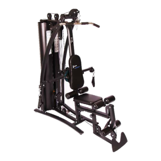
OWNER'S MANUAL
PFX – 1000 Weight Gym
asdasdasd
www.progressionfitness.ca
info@progressionfitness.ca
1-866-978-1999
IMPORTANT SAFETY INFORMATION
Be sure to read the entire manual before assembly and
operation. Also, please note the following safety
precautions:
• Before using the unit or starting any exercise program,
consult your physician. This is especially important for
anyone over the age of 65, persons with pre-existing
health problems or women that are pregnant.
• Keep children and pets away from this equipment at all
times.
• This unit should only be used on a level surface and is
intended for indoor use only. We recommend placing an
equipment mat under the unit to protect the floor or
carpet.
• Do not use until the machine has been fully assembled
and inspected for correct performance in accordance
with the manual.
• Always wear proper clothing and walking/running shoes
when exercising. Do not wear loose fitting clothing that
could get caught in the equipment.
• Always examine unit before use to ensure all parts are in
working order.
• Progression assumes no responsibility for equipment
failure if unauthorized equipment modifications are
made.
• Progression assumes no responsibility for personal
injury or property damage sustained by or through the
use of this product.
1
Advertisement

Related Manuals for Progression Fitness X-plode PFX-1000


Summary of Contents for Progression Fitness X-plode PFX-1000
- Page 1 asdasdasdasd IMPORTANT SAFETY INFORMATION Be sure to read the entire manual before assembly and operation. Also, please note the following safety precautions: OWNER’S MANUAL • Before using the unit or starting any exercise program, consult your physician. This is especially important for anyone over the age of 65, persons with pre-existing health problems or women that are pregnant.
- Page 2 PART # PART NAME SIZE Seat Cushion Frame Bracket PARTS Leg Extension Steel Rod PART Foot Plate PART NAME SIZE Threaded Pivoting Rod Base Frame 10mm Spring Washer Ø10 Weight Stack Column Pin Roller Pad Ø100*175 Guide Rod Roller Pad Inside Cap 10mm Flat Washer Ø10 Roller Pad Outside Cap...
- Page 3 PARTS...
- Page 4 asdasdasdasd ASSEMBLY Step 2: Step 1: With assistance, line up Locate and attach the rubber feet the main centre frame (part #14) (part #43)/stabilizers to the over top of the guide rods and over bottom of the base frame. top of the bolt holes on base frame. Locate the two rubber donuts Secure (part #14) to the (part #6) and the two guide rods...
- Page 5 asdasdasdasd ASSEMBLY CONT’D Step 3: Locate both of the large curved frame supports (part # 21 and 22) and secure the bottom to the base support frame with six M12x60mm bottom frame bolts (part#15), six 12mm washers (part#16) and six nuts (part#17).
- Page 6 asdasdasdasd ASSEMBLY CONT’D Step 4: Secure the fly arm support plate (#28) to the backrest support frame using four M12x30mm (#31) centre frame bracket bolts and four 12mm lock washers and four 12mm washers. Attach the left and right pec fly arms (#26,#27) through the rear of the fly arm support plate (#28) using two M10x20mm flyarm securing bolts (#18s) and washers (#16) into the...
- Page 7 asdasdasdasd ASSEMBLY CONT’D Step 5: Secure the seat bottom frame (#33) to the backrest support frame using two M12x70mm support plate bolts (#24), two 12mm washers (#16) and two M12 nuts (#17). Tighten bolts. Attach the leg extension arm (#35) to the leg extension base frame (#33) with two M10x20mm Centre frame bracket bolts (#5), two 10mm washers (#4) and the threaded pivoting rod (#37) on inside.
- Page 8 asdasdasdasd ASSEMBLY CONT’D Step 6: Thread lat pulldown cable (#51) over pulley #1, pulley #2, down and through the middle of the pulley adjustment tension plate (#45), back up and over pulley #4, over pulley #5 and then threaded into the top of the weight stack. Make sure the cabling has not been threaded over anything other than the nylon pulleys.
- Page 9 asdasdasdasd ASSEMBLY CONT’D Step 7: Thread the leg extension cable (#54) under pulley #1, under pulley #2, over pulley #3, under pulley #4, up through the middle of the double pulley bracket #5, back down under pulley #6 and back upwards to thread into the bottom of the horizontal double pulley bracket #52 (used for fly arm cable in step 8).
- Page 10 asdasdasdasd ASSEMBLY CONT’D Step 8: Attach the back pad (#58) to the back rest support frame using four M8x25mm bolts (#67). Remove the threaded mechanism from one side of the Pec Fly Cable (#55). iii. Thread the cable through the pec fly arm pulley #1, then to inside of pulley #2 on back of pec fly arm, through bottom of pulley #3, then up over top of pulley #4 and back down through the Horizontal...
- Page 11 asdasdasdasd ASSEMBLY CONT’D Step 9: Attach the seat pad (#60) to the leg extension frame using two M8x40mm bolts (#61). Attach the left and right side weight shrouds (#66) using eight M8x16mm weight shroud bolts (#59) and eight 8mm locking washers (#10). Slide the following over the leg extension steel rod on each side: Roller pad inside cap (#40), roller pad iii.
Need help?
Do you have a question about the X-plode PFX-1000 and is the answer not in the manual?
Questions and answers