Advertisement
Quick Links
Advertisement

Related Manuals for Progression Fitness 7000E


Summary of Contents for Progression Fitness 7000E
- Page 1 ELLIPTICAL TRAINER 7000E...
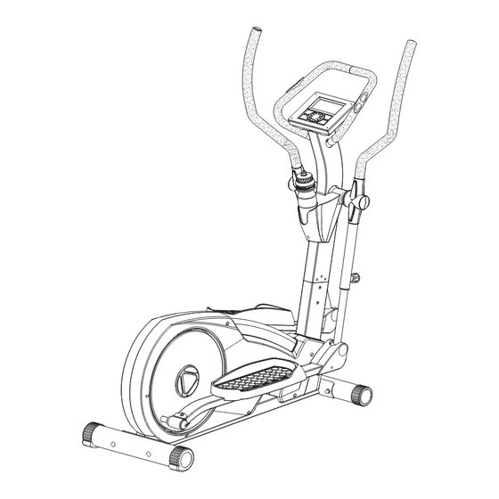
- Page 2 Main frame Monitor E3 Adaptor TOOLS Central support tube Front handlebar Rear stabilizer Side handlebar Front stabilizer Water bottle Handlebar joint cover Pedal tube joint cover Pedal (H1) (H3) (H5) (H2) (H4) (H6) (J1) Knob (J2) Screw M5x8L (J3) Screw M4x12L (J4) Washer M6 (J5) Spring washer M6 (J6) Knob...
- Page 3 ASSEMBLY FOR REAR STABILIZER First, remove the bolts(C4), washer(C5),spring washer(C6) and nuts(C7) from the rear stabilizer(C).Use two bolts(C4) through the rear stabilizer(C) to attach to the bracket at the back of the main frame(A). Then, secure it with washer(C5), spring washer(C6) and nut(C7). After you complete Figure 1 &...
- Page 4 ASSEMBLY FOR CENTRAL SUPPORT TUBE First, remove the bolts(B21), spring washers(B14) and washer(B13) from the central support tube(B). Step1. Connect the cable(B5) & (A15). Step2. Assemble the central support tube(B) onto the main frame(A) with bolts(B21), spring washer(B14) and washer(B13). Attention: when pushing the tubes ASSEMBLY FOR MONITOR...
- Page 5 close up drawing for the (G4) assembly position. for the (J1) assembly position. ASSEMBLY FOR SIDE HANDLEBAR Step1. Pull up right connect tube(A43) and adjust to the suitable position so 4 holes are available when loosing the pop-pin in the middle tube(B) insert tube(A43) into(B) tube and secure with pop-pin(J1).
- Page 6 ASSEMBLY FOR SIDE HANDLEBAR JOINT COVERS Step1. Connect right side handlebar joint covers (H1 & H2) onto side handlebar(G) and secure with screws(J3). Repeat Step1 on left side handlebar joint covers. ASSEMBLY FOR FRONT HANDLEBAR First, remove the bolts(B7), from the central support tube(B) and remove the screw(F3) from the handlebar clip of the front handlebar(F).
- Page 7 SIDE PEDAL JOINT COVERS Connect right side pedal tube joint covers(H3 & H4) onto pedal joints and secure with screws(J2). Repeat again on left side pedal tube joint covers. ASSEMBLY FOR PEDAL Assemble the iron bracket(J10) on the pedal tube and secure it by screw(J7), spring washer(J9) and washer(J8),which are located in the pedal tube already.
-
Page 8: How To Move The Machine
HOW TO MOVE THE MACHINE The front stabilizer has built-in transport wheels. To move the machine, stand at the front and lift it up until the weight of the machine is transferred to the transport wheels. You can now easily move the machine to a new location. ... - Page 9 - 8 -...
-
Page 10: Parts List
PARTS LIST DESCRIPTION Q'TY DESCRIPTION Q'TY MAIN FRAME CENTRAL SUPPOR TUBE MAGNETIC FLYWHEEL WATER BOTTLE FLAT WASHER SENSOR WIRE HAND PULSE SENSOR WIRE TENSION PULLEY BOLT PIPE BUSHING FLAT WASHER SHAFT SCREW BEARING BEARING BUSHING E CLIP CONNECT TUBE MAGNETIC HOUSING FLAT WASHER SPRING WASHER SCREW... -
Page 11: Button Functions
1. LCD display (with all segments): 2. BUTTON functions: In stop mode, th mode is to confirm all exercise data MODE and enter into program. To select training mode and adjust function value up. To start or stop exercise. SELECTOR To select training mode and adjust function value down. - Page 12 4. Operation Procedure: 4-1 Power on: Install power supply. Computer will make a long beep sound and then display all segments for 2 seconds, then show distance on the machine. (as figure 1) Console will ask user to set up clock first and then enter into standby mode. User may turn UP and DOWN selector button to select a exercise program from P1 to P12, then press MODE to confirm.
- Page 13 MANUAL mode FUNCTION SELECT FUNCTION SELECT MANUAL SELECT TOTAL RESET PRESS TOTAL RESET PRESS PRESS PRESS CLOCKWISE OR MODE MODE MODE CLOCKWISE OR CLOCKWISE OR ANTI-CLOCKWISE ANTI-CLOCKWISE ANTI-CLOCKWISE FUNCTION SELECT FUNCTION SELECT START / STOP PRESS PRESS MODE MODE CLOCKWISE OR CLOCKWISE OR ANTI-CLOCKWISE ANTI-CLOCKWISE...
- Page 14 PROGRAM Profile for P2 to P11: In P12 program (HR control), AGE information needs to be entered. User may press UP or DOWN button to set the AGE (default is 25), then press MODE to enter. After AGE is set user needs to select HR level from 55%, 75%, 90% for the target pulse. (as figure 8 and 9) Figure 8 Figure 9...
- Page 15 4. RECOVERY: After exercising for a period of time, hold the handgrips and press “RECOVERY” button. All function display will stop except “TIME”. It starts counting down from 60 seconds to 0 seconds. The screen will display your heart rate recovery status with the F1,F2….to F6. F1 is the best, F6 is the worst.
- Page 16 120 Robin Cres, Saskatoon, SK S7L 6M7 1-886-978-1999...
Need help?
Do you have a question about the 7000E and is the answer not in the manual?
Questions and answers