Sign In
Upload
Download
Table of Contents
Contents
Add to my manuals
Delete from my manuals
Share
URL of this page:
HTML Link:
Bookmark this page
Add
Manual will be automatically added to "My Manuals"
Print this page
×
Bookmark added
×
Added to my manuals
Manuals
Brands
Rohde & Schwarz Manuals
Measuring Instruments
R&S ZNBT
Getting started
Rohde & Schwarz R&S ZNBT Getting Started
Vector network analyzers
Hide thumbs
Also See for R&S ZNBT
:
User manual
(1451 pages)
1
2
Table Of Contents
3
4
5
6
7
8
9
10
11
12
13
14
15
16
17
18
19
20
21
22
23
24
25
26
27
28
29
30
31
32
33
34
35
36
37
38
39
40
41
42
43
44
45
46
47
48
49
50
51
52
53
54
55
56
57
58
59
60
61
62
63
64
65
66
67
68
69
70
71
72
73
74
75
76
77
78
79
80
81
page
of
81
Go
/
81
Contents
Table of Contents
Bookmarks
Table of Contents
Table of Contents
Safety and Regulatory Information
Safety Instructions
Warning Messages in the Documentation
Korea Certification Class a
Documentation Overview
Getting Started Manual
User Manual and Help
Service Manual
Instrument Security Procedures
Printed Safety Instructions
Data Sheets and Brochures
Release Notes and Open Source Acknowledgment (OSA)
Application Notes, Application Cards, White Papers, Etc
Preparing for Use
Lifting and Carrying
Unpacking and Checking
Choosing the Operating Site
Setting up the Product
Placing the Product on a Bench Top
Mounting the Product in a Rack
Considerations for Test Setup
Connecting the Analyzer to the AC Supply
Switching the Instrument on and off
Standby and Ready State
Windows Operating System
Minimizing the VNA Application
Connecting External Accessories
Connecting a Monitor
Connecting a Keyboard
Connecting a Mouse
Connecting a Printer
Connecting a LAN Cable
Connecting a USB Cable for Remote Control
Remote Operation in a LAN
Assigning an IP Address
Using Computer Names
Remote Desktop Connection
Windows ® Firewall Settings
Instrument Tour
Front Panel R&S ZNB
Touchscreen
Function Keys
Data Entry Keys
Rotary Knob
Navigation Keys
Standby Key
Front Panel Connectors
Front Panel R&S ZNBT
Test Ports
Administrative Area
Rear Panel R&S ZNB
Rear Panel R&S ZNBT
Operating the Instrument
Manual Operation
Control Elements of the Application Window
Title Bar
Toolbar
Softtools
Menu Bar
Menu Structure
Hardkey Panel
Status Bar
Touchscreen Gestures
Working with Dialogs
Handling Diagrams, Traces, and Markers
Adding New Traces and Diagrams
Adding New Markers
Deleting Display Elements
Using Drag and Drop
Entering Data
Using Front Panel Keys
Using the Numeric Editor
Using the Analyzer's On-Screen Keyboard
Using the Windows ® On-Screen Keyboard
Scaling Diagrams
Using the Graphical Zoom
Setting the Sweep Range
Reference Value and Position
Auto Scale
Circular Diagrams
Set by Marker
Enlarging a Diagram
Performing Measurements
Transmission S-Parameter Measurement
Connecting the Instrument for Transmission Measurements
Selecting the Sweep Range and Other Parameters
Calibrating the Instrument
Evaluating Data
Saving and Printing Data
Reflection S-Parameter Measurement
Firmware Installation
Contacting Customer Support
Index
Advertisement
Quick Links
Download this manual
®
R&S
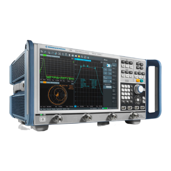
ZNB/ZNBT
Vector Network Analyzers
Getting Started
(=@0Ì2)
1316006202
Version 64
Ihr Ansprechpartner /
Your Partner:
dataTec AG
E-Mail: info@datatec.eu
>>> www.datatec.eu
Table of
Contents
Previous
Page
Next
Page
1
2
3
4
5
Advertisement
Table of Contents
Need help?
Do you have a question about the R&S ZNBT and is the answer not in the manual?
Ask a question
Questions and answers
Related Manuals for Rohde & Schwarz R&S ZNBT
Measuring Instruments Rohde & Schwarz R&S ZNB User Manual
Vector network analyzers (1451 pages)
Measuring Instruments Rohde & Schwarz R&S ZNL Series Getting Started
Vector network analyzer (95 pages)
Measuring Instruments Rohde & Schwarz R&S ZNL3 User Manual
Vector network analyzers (1014 pages)
Measuring Instruments Rohde & Schwarz R&S ZNLE3 User Manual
Vector network analyzers (1014 pages)
Measuring Instruments Rohde & Schwarz R&S ZNLE6 User Manual
Vector network analyzers (1014 pages)
Measuring Instruments Rohde & Schwarz R&S ZN-Z3x User Manual
Inline calibration system (62 pages)
Measuring Instruments Rohde & Schwarz R&S ZNA Series User Manual
Vector network analyzer (1849 pages)
Measuring Instruments Rohde & Schwarz R&S ZNA26 User Manual
Vector network analyzer (1849 pages)
Measuring Instruments Rohde & Schwarz R&S ZNA43 User Manual
Vector network analyzer (1849 pages)
Measuring Instruments Rohde & Schwarz R&S ZNA67 User Manual
Vector network analyzer (1849 pages)
Measuring Instruments Rohde & Schwarz R&S ZNB43 Getting Started
Vector network analyzers (81 pages)
Measuring Instruments Rohde & Schwarz R&S ZVL Service Manual
Vector network analyzer (170 pages)
Measuring Instruments Rohde & Schwarz R&S FSP40 Operating Manual
Spectrum analyzer (796 pages)
Measuring Instruments Rohde & Schwarz R&S FPL1000 Getting Started
Spectrum analyzer (100 pages)
Measuring Instruments Rohde & Schwarz R&S NPA101 User Manual
Power analyzers (269 pages)
Measuring Instruments Rohde & Schwarz R&S FSH-Z2 Quick Start Manual
Handheld spectrum analyzer (61 pages)
This manual is also suitable for:
R&s znb
R&s znb43
R&s znb8
R&s znb26
R&s znb4
Table of Contents
Print
Rename the bookmark
Delete bookmark?
Delete from my manuals?
Login
Sign In
OR
Sign in with Facebook
Sign in with Google
Upload manual
Upload from disk
Upload from URL


Need help?
Do you have a question about the R&S ZNBT and is the answer not in the manual?
Questions and answers