Table of Contents
Advertisement
Quick Links
08062009
1. Technical description.
1.1.
General description.
The LB5 (AWZ534) fuse block is used for power distribution in a low-voltage systems (power distribution). It
has the IN input for power connection, i.e. 10V-30V/DC or 10V-24V/AC (e.g. buffer power-supply, transformer, etc.).
The LB5 module features five independently protected AUX1...AUX5 power outputs. An AUX output has short-circuit
protection (SCP) as a fuse (F 0,5A or F 1,0A) and surge protection - varistors. Any output state is indicated by five L1...L5
LED's. A fuse failure is indicated by a proper LED switching-off, i.e. L1 for AUX1 etc. Moreover, if a failure occurs, the AW
output (L state) and the LED AW are activated. The AW output can be used for remote control of the LB5 state, e.g.
translocated optical signalling.
1.2. The diagram of the module connection (fig.1).
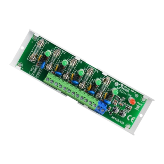
1.3 Elements and connectors of the LB5 block (fig.2, table 1).
Table 1.
Element no.
[Fig. 2]
[1]
[2]
[3]
[4]
[5]
[6]
Edition: 2nd from the 25th July of 2009
Supercedes edition: 1st from the 7th July of 2008
Fig. 1. The diagram of the LB5 module connection (example).
L1, L2, L3, L4, L5 green LED's (indicate a fuse failure)
F1, F2, F3, F4, F5 fuses in AUX circuits (+)
+IN- input of supply of the LB5 block (10V-14V)
AUX1, AUX2, AUX3, AUX4, AUX5 outputs, common terminal (-)
LED AW (red) indicating a failure of any output (fuse failure)
AW LB5 output indicating a failure of any output, OC type
(normal state hi-Z, failure L=0V), common terminal (-)
LB5
AWZ 534
v.1.1
Fuse block for power distribution.
Description
1
EN
Advertisement
Table of Contents

Related Manuals for Pulsar LB5


Summary of Contents for Pulsar LB5
- Page 1 LED’s. A fuse failure is indicated by a proper LED switching-off, i.e. L1 for AUX1 etc. Moreover, if a failure occurs, the AW output (L state) and the LED AW are activated. The AW output can be used for remote control of the LB5 state, e.g.
- Page 2 Fig.2. The view of the LB5 module. 1.4 Technical parameters: - electrical parameters (tab.2) - mechanical parameters (tab.3) Table 2. 10V÷30V/DC (-2%/+2%) Supply voltage 10V÷24V/AC (-2%/+2%) Output voltage Uaux=Uin Consumption of current by LB5 10mA@12Vdc , 40mA@30Vdc Number of inputs (power supply)
- Page 3 (transformer) separation from the network supply. The LB5 shall be mounted in a metal casing (a cubicle, a terminal device) and in order to fulfill LVD and EMC requirements the rules for power-supply, encasing and shielding shall be observed according to application.
- Page 4 WEEE Directive and is effective only with EU. THE GENERAL WARRANTY CONDITIONS 1. Pulsar K. Bogusz, Particular Partnership (the manufacturer) provides a two-year quality warranty for devices, as from the purchase date placed on a purchase proof.
Need help?
Do you have a question about the LB5 and is the answer not in the manual?
Questions and answers