Table of Contents
Advertisement
Quick Links
Advertisement
Table of Contents

Related Manuals for Pulsar Zenith 140


Summary of Contents for Pulsar Zenith 140
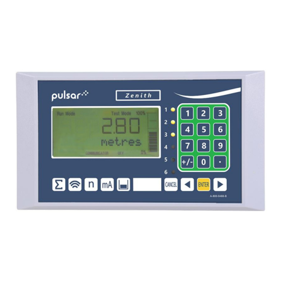
- Page 1 Zenith 140 Instruction Manual...
- Page 3 Pulsar Process Measurement Limited. WARRANTY AND LIABILITY Pulsar Measurement guarantee for a period of 2 years from the date of delivery that it will either exchange or repair any part of this product returned to Pulsar Process Measurement...
-
Page 4: Table Of Contents
Transducer ........................... 20 Voltage selector and fuse location................23 Preparation for Operation ..................... 25 Maintenance ........................25 Chapter 3 How To Use Your Zenith 140 ............... 26 Operating the Controls ....................26 Run Mode ..........................27 Program Mode ........................28 How to Access Program Mode .................. - Page 5 PULSAR MEASUREMENT Parameter Defaults ......................36 Chapter 4 Quick Setup Guide ................... 37 Enter Program Mode ....................... 37 Choose Quick Setup ......................37 Quick Setup ......................... 39 Example 1 Level Monitoring with Alarms ..............44 Example 2 Sump Control (pump down) ..............46 Chapter 5 Parameter Guide ....................
- Page 6 ZENITH 140 INSTRUCTION MANUAL mA Input ..........................68 Relay Parameters ....................... 70 Alarms ............................ 72 Pumps ............................ 79 Control ........................... 83 Miscellaneous ........................88 Pump by Time ........................89 Common Relay parameters................... 92 Pump “Advanced” Parameters ..................94 Pump Run On ........................94 Starting ..........................
- Page 7 PULSAR MEASUREMENT Display Parameters ......................126 Options ..........................126 Failsafe ..........................127 Auxiliary ..........................128 Totaliser ..........................130 mA Output Parameters ....................133 Range ........................... 133 Operation ........................... 134 Setpoint ..........................134 mA Limits ..........................135 mA Trim ..........................135 mA Failsafe .........................
- Page 8 ZENITH 140 INSTRUCTION MANUAL LED Colour ......................... 146 Watchdog ........................... 147 Daylight Saving Time ..................... 148 Device Comm........................152 RS232 Set Up ........................152 RS 485 Set Up ........................152 Remote Alarm ........................153 Test Parameters ....................... 155 Simulation .......................... 155 Hardware ..........................
-
Page 9: Chapter 1: Start Here
There are various parts of the manual that offer additional help or information as shown. Tips TIP: Look f or this ic on throu ghout your Pulsar Measu rem ent manual t o find helpful info rmation and answers to frequently asked que stion s . Additional Information... -
Page 10: About The Zenith 140
The Zenith 140 operates on the principle of timing the echo received from a measured pulse of sound transmitted in air and utilises the unique DATEM software (Digital Adaptive Tracking of Echo Movement). This is an entirely new digital mapping technique developed especially for the Pulsar Ultra range. - Page 11 PLC, to monitor level, space or distance, independently from that shown on the display. There is an RS232 port, so that the Zenith 140 can be operated remotely by a PC or other equipment.
-
Page 12: Product Specification
ZENITH 140 INSTRUCTION MANUAL Product Specification PHYSICAL Fascia Mount dimensions 200 x 112 x 108mm Weight 1.3kg Enclosure material/description Stainless steel back, ABS front and bezel Transducer Cable Extensions 2-core screened Maximum Separation 1000m (3,280 ft), 500m (1,640 ft) for mmWave... - Page 13 100 mA at 170-240 VAC (fitted as standard to wall Fuses units). 200 mA at 85-120 VAC (fitted as standard to fascia units). Pulsar Measurement operates a policy of constant development and improvement and reserve the right to amend technical details, as necessary.
-
Page 14: Eu Certificate Of Conformity
ZENITH 140 INSTRUCTION MANUAL EU Certificate of Conformity... -
Page 15: Chapter 2 Zenith 140 Installation
Pulsar Process Measurement Limited. Power Supply Requirements The Zenith 140 can operate from AC supply or from a DC battery. The AC is either 85-120V 50/60Hz or 170-240V 50/60Hz, depending on the position of the selector switch. The DC is 18-36V. In all cases the Zenith 140 will... -
Page 16: Location
When choosing a location to mount the enclosure, bear in mind the following: Ensure that the Zenith 140 is installed in a “Safe”, non-hazardous • area. For a clear view of the LCD display, it is recommended that it is •... -
Page 17: Dimensions
PULSAR MEASUREMENT Dimensions Fascia Mount The dimensions of the wall fixing holes are as shown below:... - Page 18 ZENITH 140 INSTRUCTION MANUAL The full dimensions of the fascia mount enclosure are as shown below: 200 mm 112 mm 162 mm 15mm 16mm 72mm 20mm...
-
Page 19: Terminal Connection Details
PULSAR MEASUREMENT Terminal connection details Fascia Mount The terminal details are as illustrated below:... -
Page 20: Power
ZENITH 140 INSTRUCTION MANUAL Power The Zenith 140 can operate from mains AC and automatically from DC or battery backup in the event of power failure or can be operated permanently from DC or batteries. Transducer The transducer should be installed, and connected, in accordance with the installation instructions contained in the Transducer User Guide. - Page 21 500 . Current Input (Optional) This feature is available as an option only. Please consult Pulsar for further details. The current input is an isolated (floating) mA input (to 150 V), 4 - 20mA or 0 -20mA.
- Page 22 4 for type A and 5 for type B (see above), the range is specified on the label of the sensor. This feature is available as an option only, please consult Pulsar for further details. Digital Inputs...
-
Page 23: Voltage Selector And Fuse Location
PULSAR MEASUREMENT RS2323 Serial Interface If required, you can connect to the serial interface to operate your Zenith remotely. Voltage selector and fuse location Fascia Mount The voltage selector switch and mains fuse, is located under the removable cover at the bottom of the unit, as illustrated below. - Page 24 Wall units are supplied set to 230 volts AC for safety reasons, and a 100mA fuse fitted as standard. Never operate the Zenith 140 with the terminals access cover removed. An external switch or circuit breaker should be installed near to the Zenith 140 to allow the supply to be removed during installation and maintenance.
-
Page 25: Preparation For Operation
PULSAR MEASUREMENT Preparation for Operation Before switching on, check the following: ✓ The Zenith 140 is mounted correctly and is in a ‘safe’ area. ✓ The power supply is correctly installed. ✓ The voltage selector switch is in the correct position. -
Page 26: Chapter 3 How To Use Your Zenith 140
ZENITH 140 INSTRUCTION MANUAL CHAPTER 3 HOW TO USE YOUR ZENITH 140 Operating the Controls Display The display provides information on the current mode of operation, and status of the remote communication. Whilst in the Run Mode it will display... -
Page 27: Run Mode
All modes are now described. Run Mode This mode is used once the Zenith 140 has been set up in program mode. It is also the default mode that the unit reverts to when it resumes operation after a power failure. -
Page 28: Program Mode
ZENITH 140 INSTRUCTION MANUAL Program Mode This mode is used to set up the Zenith 140 or change information already set. You must use either the built-in keypad (standard) or, alternatively the unit can be set up with a PC via the RS232 Serial Interface. -
Page 29: Hot Keys
HOT KEY RUN MODE PROGRAM MODE Total pump running hours and ∑ Not used with Zenith 140 individual pump running hours. Displays echo confidence, echo strength, height above loss limit (HALL), Not used with Zenith 140 average noise, peak noise, and... -
Page 30: Menu Keys
ZENITH 140 INSTRUCTION MANUAL Menu Keys The menu keys have the following functions: HOT KEY FUNCTION 1) Arrow keys for moving left and right around the menu system. 2) Used in test mode to simulate the level moving up and down. -
Page 31: Using The Menu System
PULSAR MEASUREMENT There are two means of editing parameters, directly or using the menu system. Each is now described. Using the Menu System The menu system has been designed to make the changing of parameters very simple. There are two levels of menu: Main Menu and Sub Menu. -
Page 32: Directly Editing Parameters
ZENITH 140 INSTRUCTION MANUAL Important Information You can tell which part of the menu system you are in, as the up/down level indicators, (arrows) next to the bar graph will indicate as follows: • Top level menu: Down arrow on, to indicate you can move down. -
Page 33: Test Mode
PULSAR MEASUREMENT Test Mode Test mode is used to simulate the application and confirm that all parameters and relay setpoints have been entered as expected. During simulation, there is a choice of whether the relays will change state (hard simulation) or not (soft simulation), but the LED’s will always change colour as programmed, and the mA output will change in accordance to the chosen mode of operation. -
Page 34: Using The Serial Interface
To log off, send the command /ACCESS:OFF To read a parameter value, send the command /Pxxx where xxx is the parameter you wish to read, and the Zenith 140 will respond with the parameter value. To set a parameter, send the command /Pxxx:yy where xxx is the parameter number, and yy is the value you wish to set it to. - Page 35 /BACKUP2 (take backup of parameters to area 2) /RESTORE1 (restore parameters from area 1) /RESTORE2 (restore parameters from area 2) Please consult Pulsar Measurement or contact your local Pulsar representative for further details and a full list of available commands.
-
Page 36: Parameter Defaults
Factory Default P930, as described in the relevant unit type parameter guide. When you first switch the Zenith 140 on, it will be reading the distance from the face of the transducer to the surface. It will be indicating in metres, as shown on the display. -
Page 37: Chapter 4 Quick Setup Guide
CHAPTER 4 QUICK SETUP GUIDE This quick set-up guide shows you how to get up and running in a few minutes in just four easy steps after installing your Zenith 140. Enter Program Mode First you need to go from run mode into program mode. Assuming the... - Page 38 ZENITH 140 INSTRUCTION MANUAL Choose Your Application There are four categories of application, which are all described at the end of this chapter. They are level, pump down (sump control), pump up (reservoir control) or customised, all with the choice of alarms and a number of pumps, dependant on application.
-
Page 39: Quick Setup
PULSAR MEASUREMENT Quick Setup Quick Setup 1 = Level 2 = Pump Down 3 = Pump Up 4 = Customised How Many Pumps Select the option 1 = One Pump specific to your 2 = Two Pumps application 3 = Three Pumps... - Page 40 ZENITH 140 INSTRUCTION MANUAL Set-up Your Application Once you have chosen the application, you will see a ‘Wait…’ message while the parameters are all calculated and stored. Next you will see the parameters needed to finalise your application, in turn, as shown below. If you know you don’t need to change from the default, you can use the right...
- Page 41 PULSAR MEASUREMENT PARAMETER DEFAULT DESCRIPTION Factory preset as a % to P213 / P214 appropriate level according Either Alarm or Level control. Relay 1 ON/OFF to the span already Depends on application. setpoints entered. See tables below Factory preset as a % to...
- Page 42 ZENITH 140 INSTRUCTION MANUAL Alarm relays, via the Quick Setup menu are entered as a % of span and are as follows: NO. OF APPLICATION PUMP NUMBER PUMPS SETPOINT SETPOINT Pump Down Pump 1 Pump 1 Pump Down Pump 2...
- Page 43 PULSAR MEASUREMENT NO. OF APPLICATION PUMP NUMBER PUMPS SETPOINT SETPOINT Pump Up Pump 1 Pump 1 Pump Up Pump 2 Pump 1 Pump Up Three Pump 2 Pump 3 Pump 1 Pump 2 Pump Up Four Pump 3 Pump 4...
-
Page 44: Example 1 Level Monitoring With Alarms
ZENITH 140 INSTRUCTION MANUAL Example 1 Level Monitoring with Alarms A vessel, containing liquid that has a variation in level that is to be monitored, with a high-level alarm set on Relay 1 and low-level alarm set on Relay 2. - Page 45 PULSAR MEASUREMENT To program the Zenith 140 for Example 1 Level Monitoring with Alarms by using the Quick Setup menu proceed as follows. If required to access Program Mode, key in the passcode 1997 and press ENTER At the Quick Setup menu press ENTER and as prompted, by the questions, select the relevant option and ENTER.
-
Page 46: Example 2 Sump Control (Pump Down)
ZENITH 140 INSTRUCTION MANUAL Example 2 Sump Control (pump down) A sump is typically used to temporarily hold water or effluent, and when the level reaches a specific point, the sump is pumped down, with the fluid being transferred to another process. - Page 47 PULSAR MEASUREMENT To program the Zenith 140 for Example 2 Sump control (pump down) by using the Quick Setup menu proceed as follows. If required to access Program Mode, key in the passcode 1997 and press ENTER At the Quick Setup menu press ENTER and as prompted, by the questions, select the relevant option and ENTER.
-
Page 48: Chapter 5 Parameter Guide
ZENITH 140 INSTRUCTION MANUAL CHAPTER 5 PARAMETER GUIDE This chapter describes all the parameters in your Zenith 140, as they appear in the menu system. Menu System Shown below is a set of charts to show you how all the various functions and features can be found using the menu system. -
Page 49: Application Menu
PULSAR MEASUREMENT Application Menu mA Input Operation Distances P100 P104 P119 Mode Measurement mA Status Units P101 P120 Transducer Low mA In P105 Empty Level P121 P102 High mA In Material P106 Span P122 Low Level In P107 Near Blanking... -
Page 50: Relays Menu
ZENITH 140 INSTRUCTION MANUAL Relays Menu Relay 1 Relay 2 Relay 3 Relay 4 Relay 5 Relay 6 P210 P220 P230 P240 P250 P260 Type Type Type Type Type Type P211 P221 P231 P241 P251 P261 Function Function Function Function... -
Page 51: Pump "Advanced" Menu
PULSAR MEASUREMENT Pump “Advanced” Menu Run On Starting Stopping Exercise Wall Cling Storm P349 P352 P348 P354 P360 P370 Prime Start Exercise Pump Stop Delay Wall Cling Level Delay Enable Disable P350 P353 P371 P355 Power Disable Idle Time Interval... -
Page 52: Digital Inputs Menu
ZENITH 140 INSTRUCTION MANUAL Digital Inputs Menu Digital Input 2 Common Digital Digital Input 1 Input 7 Digital Input 6 Input 2 – P375, Input 3 – P378 P300 P372 P390 Input 4 – P381, Input 5 – P384 Maximum... -
Page 53: Float Switch Menu
PULSAR MEASUREMENT Float Switch Menu Digital Input 2 Common Digital Digital Input 1 Input 6 Digital Input 5 Input 2 – P336, Input 3 – P339 P330 P333 P363 Input 4 – P342, Input 5 – P345 Mode Type Type... -
Page 54: Tariff Guard Menu
ZENITH 140 INSTRUCTION MANUAL Tariff Guard Menu Peak Time 2 Peak Peak Set Up Time Time Peak Time 9 PT2 – P406, PT3 – P412, P393 P400 P454 PT4 – P418, PT5 – P424, Enable PT1 Day PT1 Day PT6 – P430, PT7 - P436, PT8 –... -
Page 55: Data Logs Menu
PULSAR MEASUREMENT Data Logs Menu Tot. Audit Temperature Pump 1 Pump 2 to 5 Pump 6 P460 P521, P531 P580 P511 P561 Vol. Date 1 Min. Temp P541, P551 Pump 1 Pump 6 Pump Hours Hours Hours P461 P581 Volume 1 Min. -
Page 56: Pumped Volume Menu
ZENITH 140 INSTRUCTION MANUAL Pumped Volume Menu Set Up Conversion Breakpoints Tables P600 P610 P205 P696 Vessel Shape Level Bkpt. 1 Pump Vol. Reset Enabled Bkpts. P611 P601 Vol. Bkpt. 1 P206 P697 As Required Settle Time Vol. Dimension 1... -
Page 57: Efficiency Menu
PULSAR MEASUREMENT Efficiency Menu Set Up P187 Pump Effic. P188 Calib. Delay P189 Cal. Duration P190 Persist Cnt. P191 Demote Pumps P192 Demote Flags P193 Calib. Pumps... -
Page 58: Display Menu
ZENITH 140 INSTRUCTION MANUAL Display Menu Options Fail Safe Auxiliary Bargraph Totaliser P800 P808 P820 P810 P829 Fail Mode Totaliser Display Units Bargraph Units P809 P811 P821 P801 Fail Time Alarms Totaliser (R) Decimal Places P812 P822 Pumps Totaliser P802... -
Page 59: Ma Output Menu
PULSAR MEASUREMENT mA Output Menu Allocation Range Operation Setpoint Limits Trim Fail Safe P834 P831 P838 P840 P841 P830 P836 mA Out Fail mA Out Allocation Value Range Mode Limit Mode Trim P835 P837 High P839 High High Limit Value... -
Page 60: Stability Menu
ZENITH 140 INSTRUCTION MANUAL Stability Menu Damping Indicator Rate Filters P870 P872 P874 P880 Fill Fill Rate Update Gate Mode Damping Indicator P875 P881 P871 P873 Rate Time Fixed Distance Empty Empty P876 P882 Damping Indicator Rate Distance Process Filter... -
Page 61: System Menu
PULSAR MEASUREMENT System Menu Date System Daylight Passcode Backup & Info Colour Saving Time P921 P925 P926 P931 P935 P970 Enable Code Parameter Software Date Backup Revision Colour Enable P922 P931 Passcode P927 Time P936 P971 Hardware Alarm P932 Revision... -
Page 62: Device Comm Menu
ZENITH 140 INSTRUCTION MANUAL Device Comm Menu Remote RS232 RS485 Setup Alarm Setup (Optional) If Comms. If Comms. P144 Comms Baud Type is Type is Call Type Profibus Modbus P145 P130 Tel. No. 1 Device Mode P146 Tel. No. 2... -
Page 63: Test Menu
PULSAR MEASUREMENT Test Menu Simulation Hardware P980 P990 Simulate Self Test P981 P991 Increment Hardware Test P982 P992 Rate mA Out Test P983 P993 Start Level mA In Test P984 P994 Incremental Transducer Test Change P995 Keys Test P996 Relay Test... -
Page 64: Application Parameters
*12 = dBR8 Transducer is a mmWave radar. Range 0.077 to 8 metres Important Notice *Please consult your local Pulsar distributor for the versions of firmware that the mmWAVE radars are available in. P102 Material This parameter should be set to the type of material being monitored. - Page 65 Use this parameter to set the second input device when using in Average or Differential Mode, and P101 Transducer = 0 (Auxiliary Input). OPTION DESCRIPTION Use the optional mA input (Please consult Pulsar for 0 = None (Default) availability). 1 = dB3 Transducer is a dB3.
-
Page 66: Dimensions
ZENITH 140 INSTRUCTION MANUAL Dimensions P104 Measurement Units This parameter sets the units you want to use for programming and display. OPTION DESCRIPTION 1 = metres (Default) All units of measurement are Metres 2 = cm All units of measurement are Centimetres... - Page 67 PULSAR MEASUREMENT P107 Span This parameter is the distance from the face of the transducer that is not measurable and is pre-set to the minimum value dependant on the Transducer (P101) selected. It should not be set to less than this figure, but can be increased, typically to ignore close in obstructions.
-
Page 68: Ma Input
ZENITH 140 INSTRUCTION MANUAL mA Input The 4-20 mA (Auxiliary) input is available as an option (Consult Pulsar for details of availability), and can be used to replace the transducer for applications where an ultrasonic transducer cannot be used. P119 mA Status... - Page 69 PULSAR MEASUREMENT P125 High mA Trim This parameter allows you to “calibrate” the Zenith to the High mA Input from the device being used. If the expected high value, from the device connected to the mA Input, is not displayed, then you can trim it using this parameter.
-
Page 70: Relay Parameters
ZENITH 140 INSTRUCTION MANUAL Relay Parameters All relay related parameters are prefixed with a 2**. The second digit of the three-figure parameter number denotes the relay number as follows: 21* parameters for Relay 1 22* parameters for Relay 2 23* parameters for Relay 3... - Page 71 PULSAR MEASUREMENT P210, 220, 230, 240, 250, 260 - Relay Type This parameter defines what type each relay should be, see the table below for available options: OPTION DESCRIPTION Relay is not in use or programmed and the LED will 0 = Not in use (Default) always be off.
-
Page 72: Alarms
ZENITH 140 INSTRUCTION MANUAL Alarms P210, 220, 230, 240, 250, 260 = 1 (Alarm) The second parameter for each relay determines the function of the alarm. P211, 221, 231, 241, 251, 261 – Relay Function OPTION DESCRIPTION 0 = Off (Default) Relay will not operate. - Page 73 PULSAR MEASUREMENT OPTION DESCRIPTION 15 = Tariff Alarm Alarm is raised when the unit enters Tariff Guard mode. (Available in firmware Tariff Guard enable (P393) must be set to ‘1’ for this option v7.5.1 and greater to be selectable. No setpoints are required...
- Page 74 ZENITH 140 INSTRUCTION MANUAL The third parameter for each relay determines the Alarm ID for the relay you wish to set. P212, 222, 232, 242, 252, 262 – Relay Alarm ID When P211, 221, 231, 241, 251, 261 = 4 (Loss of Echo) or 5 (Loss of Clock).
- Page 75 PULSAR MEASUREMENT OPTION DESCRIPTION SETPOINTS Same as 4 = Lo, but 5 = LoLo different identifier Relay Setpoints, P213, 223, 233, 243, 253, 263 and Relay goes “ON” if value P214, 224, 234, 244, 254, is inside the zone 6 = In bounds...
- Page 76 ZENITH 140 INSTRUCTION MANUAL P212, 222, 232, 242, 252, 262 Relay Alarm ID When P211, 221, 231, 241, 251, 261 = 7 (Device Fail) This parameter defines which failed device relay, the alarm should respond to, as follows. OPTION DESCRIPTION SETPOINTS Relay goes “ON”...
- Page 77 PULSAR MEASUREMENT P212, 222, 232, 242, 252, 262 Relay Alarm ID When P211, 221, 231, 241, 251, 261 = 8 (Device Alarm) This parameter defines which digital input, the alarm should respond to, as follows. OPTION DESCRIPTION SETPOINTS Relay goes “ON” when a device...
- Page 78 ZENITH 140 INSTRUCTION MANUAL When P211, 221, 231, 241, 251, 261 = 1 (Level), 2 (Rate of Change) or 3 (Temperature) or 6 (Efficiency) P213, P223, P233, 243, 253, 263 - Relay Setpoint 1 Determines the “ON” or “OFF” point for the alarm according to the ID selected.
-
Page 79: Pumps
PULSAR MEASUREMENT Pumps P210, 220, 230, 240, 250, 260= 2 (Pump) When a relay is being used for a pump function, the second parameter determines the pump duty that will be used to determine the operating cycle. P211, 221, 231, 241, 251, 261 – Relay Function... - Page 80 ZENITH 140 INSTRUCTION MANUAL PUMP DUTY DESCRIPTION First pump comes on, if it cannot cope, it goes off and next pump comes on (duty backup). This continues until the last pump comes on and if it cannot cope the first pump comes back on to...
- Page 81 PULSAR MEASUREMENT PUMP DUTY DESCRIPTION The first pump switched on is the first pump to be switched off, regardless of the set points, so the setpoints are dynamically changed to enable this. If a pump fails to meet the demand (due to malfunction, intake blockage and so on), then it is stopped, and another pump shall take over.
- Page 82 ZENITH 140 INSTRUCTION MANUAL The third parameter for each relay determines the pump group. You can have two groups of pumps, and all similar duties within that group will operate together. P212, 222, 232, 242, 252, 262 – Relay Pump Group...
-
Page 83: Control
PULSAR MEASUREMENT Control P210, 220, 230, 240, 250, 260 = 3 (Control) When a relay is being set as a control relay, the second parameter that will be displayed in the menu determines its function. P211, P221, P231, 241, 251, 261 - Relay Function, This function allows the relay to be assigned to specific control functions and mainly work in relation to time. - Page 84 ZENITH 140 INSTRUCTION MANUAL OPTIONS DESCRIPTION Relay will energise “ON” when Flush condition is in effect and goes off when Flush condition is cleared. A relay being used for Flush Valve/Pump must be assigned to one of the main pumps in use. Flush relay Alarm ID (P212, 222, 232, 242, 252, 262) is used to enter the relay number, to which the assigned pump is connected.
- Page 85 PULSAR MEASUREMENT OPTIONS DESCRIPTION Relay will energise “ON” when a differential condition is in effect and, de-energise “OFF” when the differential conditions cease. Two setpoints are required, Differential 6 = Differential control “ON”, (P213, 223, 233, 243, 253, 263) and Control Differential control, “OFF”...
- Page 86 ZENITH 140 INSTRUCTION MANUAL P211, 221, 231, 241, 251, 261 =2 (Storm) Relay Setpoint 1 is entered in values of Measurement Units (P104) See the appropriate relay function tables (P211, 221, 231, 241, 251, 261) for further information. P211, 221, 231, 241, 251, 261 =3 (Aeration)
- Page 87 PULSAR MEASUREMENT P211, 221, 231, 241, 251, 261 =3 (Aeration) Relay Setpoints are entered in Minutes to set Time Period that the relay will remain ON. See the appropriate relay Function tables (P211, 221, 231, 241, 251, 261) for further information.
-
Page 88: Miscellaneous
ZENITH 140 INSTRUCTION MANUAL Miscellaneous P210, 220, 230, 240, 250 = 4 (Miscellaneous) When a relay is set to be a miscellaneous relay, the second parameter determines its function. P211, 221, 231, 241, 251, 261 – Relay Function This function allows the relay to work in relation to a clock or a specific event and will be set to activate in relation to Real Time. -
Page 89: Pump By Time
PULSAR MEASUREMENT The third parameter has no function when miscellaneous relay is chosen and will not be displayed. The fourth parameter, and fifth parameter, are set to determine the switch points, “ON” and “OFF” for the relay. See miscellaneous function table (P211, 221, 231, 241, 251, 261) for further information. - Page 90 ZENITH 140 INSTRUCTION MANUAL P211, P221, P231, P241, P25, 2611 - Relay Function, This parameter defines which pump duty the relay should respond to as follows. PUMP DUTY DESCRIPTION 0 = Off (Default) Relay is always de-energised All pumps are used to assist each other (run at the same time) and each pump has its own setpoints.
- Page 91 PULSAR MEASUREMENT PUMP DUTY DESCRIPTION 5= Duty backup and assist First pump comes on, if it cannot cope, it goes off and next pump comes on (duty backup). This continues until the last pump comes on and if it cannot cope the first pump comes back on to assist...
-
Page 92: Common Relay Parameters
ZENITH 140 INSTRUCTION MANUAL When a relay is being used for a pump by time function, then the sixth parameter will determine the maximum time the pump will be allowed to run before it is switched off and the next pump takes over. - Page 93 PULSAR MEASUREMENT P217, P227, P 237, P247, P257, 267 - Relay Closures The Zenith will record how many times each relay is closed, this parameter displays the number of times the relay has activated since the relay has been in use. It can be reset with any value.
-
Page 94: Pump "Advanced" Parameters
ZENITH 140 INSTRUCTION MANUAL Pump “Advanced” Parameters The following parameters are used to set the “Advanced” Pump features. Pump Run On This feature is used to periodically allow the pumps to continue operating below their normal “OFF” point, to discharge any sediment that may have settled at the bottom of the vessel. -
Page 95: Stopping
PULSAR MEASUREMENT Stopping If required, this feature will prevent pumps, with a common “OFF” point being switched off all at the same time pumps will be switched “OFF” in turn as determined by the delay set in P348 Stop Delay. -
Page 96: Wall Cling
ZENITH 140 INSTRUCTION MANUAL Wall Cling To reduce material build up, (such as fat), on the wall of the sump or vessel, at the “normal” material level the pump setpoints can be varied within a specified band. For Pump Down applications the relay setpoints for the pumps will be... -
Page 97: Digital Inputs
PULSAR MEASUREMENT Digital Inputs About Digital Inputs The digital inputs are used to provide the Zenith with information on the operational status and condition of pumps, valves, and other process control devices. Based on the information supplied, by the inputs, the Zenith, will make intelligent decisions and modify its control regime to meet the demand of the prevailing operational requirements. - Page 98 ZENITH 140 INSTRUCTION MANUAL Input Function Individual inputs can be configured for any one of a number of Functions as determined by P373, 376, 379, 382, 385, 388, 391 these functions are as follows: OPTIONS DESCRIPTION Input will provide a signal indicating a “failure” or the presence of a “run”...
- Page 99 PULSAR MEASUREMENT Device Fail The digital inputs are used to indicate a ‘fail’ situation which effect devices, which are connected to the relay outputs of the Zenith, e.g. failure of a pump, screen, valve, etc. This information is then used to initiate changes to the Zeniths control regime to meet the demands of the situation.
- Page 100 ZENITH 140 INSTRUCTION MANUAL The decision on whether or not to attempt to start the failed pump on subsequent pump cycles will be determined by P300 Max. Attempts. Once the number of attempts stipulated have been made the pump will be put out of service until such time the Device Fail input is cleared by a Reset (P391 = 4) on Digital Input 7.
- Page 101 PULSAR MEASUREMENT When the duty switch is in the “auto” position, no signals are present on either Digital Input 3 or Digital Input 4 and devices will run in the “auto” mode, as determined by the Zenith, in accordance with its programmed settings.
- Page 102 ZENITH 140 INSTRUCTION MANUAL Consider the example of an application using 2 pumps. Each pump is connected and controlled by one of the Zenith relay outputs, the pump duty and setpoints have been programmed as detailed in Using the Relays, earlier in this chapter.
-
Page 103: Digital Input Parameters
PULSAR MEASUREMENT Override A digital input can be assigned to receive an input, which will override the setpoints of the pumps and start them, as determined by the Override Level (P306) and providing the level is above the Min. Override (P303), immediately after the expiry of the Override Delay (P302). - Page 104 ZENITH 140 INSTRUCTION MANUAL P301 Switch Mode When an external duty switch is used this can be connected via the digital inputs and facilitate the selection of the duty device manually, thereby overriding the duty programmed within the unit. This parameter determines the type of switch in use.
-
Page 105: Digital Input
PULSAR MEASUREMENT P305 Input Filter This parameter is used to ignore spurious changes of state on the digital inputs and determines the time that a change of state has to be present before it is recognised as a valid input. - Page 106 ZENITH 140 INSTRUCTION MANUAL P373, 376, 379, 382, 385, 388, 391 Function This parameter will set the function of the digital Input. OPTIONS DESCRIPTION Digital input is used to Fail, (put out of service), a 1 = Device Fail device connected to the relay specified in P374,...
-
Page 107: Float Switch (Fs) Backup
PULSAR MEASUREMENT Float Switch (FS) Backup About Float Switch Backup This digital feature is used with a float switch, where it can be used alongside a transducer or as a backup method for when a transducer goes into failsafe. The high input will have a timer and a level set point, which will allow for the unit to power on every pump below the set point for the specified amount of time as set in P332 Pump Run Time. -
Page 108: Digital Input
ZENITH 140 INSTRUCTION MANUAL Digital Input The following parameters are used to configure the use of the digital inputs. P333, 336, 339, 342, 345, 363 Type Determines the way digital inputs will be recognised by the Zenith. OPTIONS DESCRIPTION Zenith recognises a closed condition, D.C. signal 1 = Input N.C. -
Page 109: Tariff Guard
PULSAR MEASUREMENT Tariff Guard Set Up P393 Enable This parameter determines if Energy Saving is in use or not. OPTIONS DESCRIPTION 0 = Off (Default) Energy saving is switched Off 1 = On Energy saving is switched On ‘Tariff active’ will appear on the Aux display of the unit when unit is in Tariff Guard mode. - Page 110 ZENITH 140 INSTRUCTION MANUAL P398 Overflow Level This parameter determines the maximum level to which the vessel will be allowed to fill. Should this level be reached all pumps will be switched ON, to draw the level down, as required, irrespective of the control sequence in operation.
- Page 111 PULSAR MEASUREMENT P402, 408, 414, 420, 426, 432, 438, 444, 450, 456 PT Start Pk. This parameter sets the date on which the “Peak Time” will start. Enter the desired Start Date in DD:MM format. P403, 409, 415, 421, 427, 433, 439, 445, 451, 457 PT End Pk.
-
Page 112: Data Log Parameters
ZENITH 140 INSTRUCTION MANUAL Data Log parameters The data log parameters contain the following information: Totaliser Audits P460 to P479 Total Audits When Pump Volume is enabled, parameters P460-P479 show the date and pumped volume total for the last ten days, the first on the list are the most recent and last ones are the oldest. -
Page 113: Pump Logs
PULSAR MEASUREMENT P584 Maximum Temperature Date This parameter displays the date when the maximum temperature was recorded. P585 Maximum Temperature Time This parameter displays the time when the maximum temperature was recorded. P586 Current Temperature This parameter displays the current temperature. -
Page 114: Pumped Volume
ZENITH 140 INSTRUCTION MANUAL P515 Pump 1 Efficiency This parameter displays the current value for Pump 1 Efficiency, which is used to calculate the pump efficiency and will update with any change to the Pump Draw Rate (P514). P516 - P521 Pump 2 These parameters contain the same information as above for Pump 2. - Page 115 PULSAR MEASUREMENT P207 Inflow Method This parameter determines which method is used to calculate the inflow of material during a pump down cycle. OPTIONS DESCRIPTION 0 = No Inflow Inflow during pumping is not calculated Average between Inflow at time pump started and...
-
Page 116: Volume
ZENITH 140 INSTRUCTION MANUAL Volume Your Zenith provides a variety of volume calculation features, with 11 pre- programmed vessel shapes. See Vessel Shape (P600) for more information. For each vessel you will need to know the dimensions (P601-603) in Measurement Units (P104) which are required to calculate the volume (P604) which will be displayed in the selected Volume Units (P605). - Page 117 PULSAR MEASUREMENT Cylinder diameter P600 = 2 Cylindrical Cone and height of Base bottom P600 = 1 Rectangular Flat Width and Breadth Base Cylinder diameter P600 = 4 Parabola Base and height of bottom P600 = 5 Flat Sloped Base...
- Page 118 ZENITH 140 INSTRUCTION MANUAL P600 VALUE VESSEL SHAPE DIMENSIONS DESCRIPTION Width and breadth P600 = 7 Rectangular flat of rectangular section and height sloped base of bottom P600 = 8 Horizontal Cylinder diameter cylinder with flat ends and tank length...
- Page 119 PULSAR MEASUREMENT P601-P603 Vessel Dimensions These three parameters are used to enter the dimension required to calculate the volume. The dimensions required are as shown below and are entered Measurements Units (P104). VESSEL SHAPE P601 P602 P603 P600 = 0...
- Page 120 ZENITH 140 INSTRUCTION MANUAL P605 Volume Units This parameter determines the units that you wish to display, for volume conversion. It is used in conjunction with P607 (maximum volume), and the units are shown on the display (subject to P810). The choices are:...
-
Page 121: Breakpoints
PULSAR MEASUREMENT Breakpoints P610-P673 Level/Volume Breakpoints These parameters are used to create a profile of the vessel when P600=11 (universal linear) or P600=12 (universal curved). You should enter breakpoints in pairs, a reading for level and its corresponding volume. The more pairs you enter, the more accurate the profile will be. -
Page 122: Tables
ZENITH 140 INSTRUCTION MANUAL Universal Curved (P600=12) This volume calculation creates a curved approximation of the level/volume relationship, and works best if the vessel is non-linear, and there are no sharp angles. You should enter 2 level/volume breakpoints at the minimum and maximum levels, and several for each place where the vessel has got an arc. -
Page 123: Pump Efficiency
PULSAR MEASUREMENT Pump Efficiency Set Up P187 Pump Efficiency This parameter determines whether pump efficiency is enabled or disabled. OPTIONS DESCRIPTION 0 = Off (Default) Pump efficiency is disabled 1 = On Pump efficiency is enabled P188 Calib. Delay This parameter is used to set a delay, after all pumps have stopped, to allow... - Page 124 ZENITH 140 INSTRUCTION MANUAL P191 Demote Pumps. When an efficiency alarm is being used, this parameter will determine if a pump is to be demoted to the last pump in the duty cycle on activation of the alarm. When Demote Pump is enabled and the efficiency alarm is...
- Page 125 PULSAR MEASUREMENT P192 Demote Flags This parameter will indicate, in a binary number format as detailed below, which pumps, if any, have been demoted. Any demoted pump(s) can be reset by entering “0”. 0 = None 16 = Pump 5...
-
Page 126: Display Parameters
ZENITH 140 INSTRUCTION MANUAL Display Parameters Options P800 Display Units This parameter determines whether the reading displayed is in Measurement Units (P104), or as a percentage of span. OPTION DESCRIPTION 1 = Measured (Default) Display is in selected unit’s dependent in Mode (P100) -
Page 127: Failsafe
PULSAR MEASUREMENT P805 Display Source This parameter determines which input the display will relate to, it is automatically set to the correct option when selecting the Mode P100, and Xducer P101, under normal circumstances it will not require changing. OPTION... -
Page 128: Auxiliary
ZENITH 140 INSTRUCTION MANUAL P809 Failsafe Time In the event of a failsafe condition the failsafe timer determines the time before failsafe mode is activated. Default = 2mins If the timer activates, the unit goes into failsafe, as determined by P808 (Display), P218, 228, 238, 248, 258, 268 (Relays) and P840 (mA Output). - Page 129 PULSAR MEASUREMENT P812 Pump Messages This parameter determines whether notification messages are displayed on the auxiliary line of the display in run mode when a pump or general control relay is switched on or off. The message is in the form “General 1 ON”, where the number displayed is the number of the relay.
-
Page 130: Totaliser
ZENITH 140 INSTRUCTION MANUAL Displays level from transducer 2 3 = Xducer 2 P816 Totaliser (R) This parameter determines whether the resettable totaliser will be displayed in the auxiliary line of the display in run mode. When selected, the auxiliary display will scroll between the resettable totaliser and the totaliser units selected. - Page 131 PULSAR MEASUREMENT P823 Totaliser Multiplication Factor This parameter determines the number of decimal places in the totaliser during run mode. It can be set between 1 and 3. Default = 2 Use this parameter if the totaliser increments by to large or small amount, enter the factor by which the actual flow rate is multiplied by before incrementing the totaliser.
- Page 132 ZENITH 140 INSTRUCTION MANUAL Bargraph P829 Bargraph By default, the bar graph will be representative of the reading obtained, as determined by the Mode P100. When P100 = 4 (Average) or 5 (Differential) the bar graph can be assigned to be representative of the level on any of the two points of measurement.
-
Page 133: Ma Output Parameters
PULSAR MEASUREMENT mA Output Parameters Range P830 mA Range This parameter determines the range of the mA output, from the following: OPTION DESCRIPTION 0 = Off mA output disabled mA output directly proportional to the mA mode 1 = 0 to 20 mA (P831), so if the reading is 0% the output is 0 mA. -
Page 134: Operation
ZENITH 140 INSTRUCTION MANUAL Operation P831 mA Mode This parameter determines how the mA Output relates to what is measured. By default, it operates the same as the display (P100), but it can be set to operate as follows: OPTION... -
Page 135: Ma Limits
PULSAR MEASUREMENT mA Limits P836 mA Low Limit This parameter sets the lowest level that the mA output will drop to, the default is 0mA, but you can override this if the device you connect to cannot for example accept less than 2mA, yet you want to use the 0-20mA range. -
Page 136: Ma Failsafe
ZENITH 140 INSTRUCTION MANUAL mA Failsafe P840 mA Failsafe Mode This parameter determines what happens to the mA output in the event of the unit going into fail-safe mode. The default is to do the same as the system fail-safe (P808), but this can be overridden to force the mA output... -
Page 137: Compensation Parameters
PULSAR MEASUREMENT Compensation Parameters Offset P851 Measurement Offset The value of this parameter is added to the measured distance, in Measurement Units (P104). This Offset will be added to the level, as derived from the transducer, and will affect everything including the reading on the display, the relay setpoints and the mA output. -
Page 138: Velocity
ZENITH 140 INSTRUCTION MANUAL P853 Allocation This parameter indicates which transducer is being used to obtain the temperature, in the case of the Zenith this can be viewed but cannot be changed. OPTION DESCRIPTION 0 = Xducer 1 (Default) Temperature obtained from Xducer 1... -
Page 139: Stability Parameters
PULSAR MEASUREMENT Stability Parameters Damping Damping is used to damp the display, to enable it to keep up with the process but ignore minor surface fluctuations. P870 Fill Damping This parameter determines the maximum rate at which the unit will respond to an increase in level. -
Page 140: Filters
Calculated, P880=1 then the gate width is automatically calculated and updated according to the values of P870, P871, P874, P875 and P876. Please consult Pulsar for further information and assistance on changing the value of this parameter. P881 Fixed Distance... -
Page 141: Echo Processing Parameters
PULSAR MEASUREMENT P882 Process Filter This parameter determines the number of ‘cycles’ that will be taken before a change in level is processed and the display updated. OPTION DESCRIPTION 1 = Fast level will be updated every cycle 2 = Medium... -
Page 142: Transducer 2 Status
P905 Sensitivity 1 This parameter determines the sensitivity of the unit. Please consult Pulsar for further information and assistance on changing the value of this parameter. -
Page 143: Datem Parameters
PULSAR MEASUREMENT DATEM Parameters The following two parameters are used to make changes to the DATEM trace such as setting it to its default value or using it to select a particular echo, both parameters are accessed directly by simply entering Program Mode then typing in the parameter number and pressing ENTER. -
Page 144: System Parameters
ZENITH 140 INSTRUCTION MANUAL System Parameters Passcode P921 Enable Code Enables the passcode (P922), which means the passcode must be entered to go into program mode. If disabled (set to 0), then no passcode is required, and ENTER is used to enter program mode. Default =1 (Enabled) P922 Passcode This is the passcode that must be used to enter program mode. -
Page 145: System Information
PULSAR MEASUREMENT System Information The following three parameters do not affect how the unit performs, but details, contained in them, may be required, by Pulsar, when making technical enquiries. P926 Software Revision This parameter will display the current software revision. It is read only and cannot be changed. -
Page 146: Date & Time
ZENITH 140 INSTRUCTION MANUAL Date & Time The date and time is used, to control specific relay functions and date stamp certain events that are contained in the Data Logs. It is also used in conjunction with the system watchdog that keeps an eye on the times the unit has started. -
Page 147: Watchdog
PULSAR MEASUREMENT P937 Pump Relay Colour This parameter selects the colour that a pump relay should be when it is in its “ON” state. The default is 2 = green, but can be changed to ‘no colour’, red or yellow. -
Page 148: Daylight Saving Time
ZENITH 140 INSTRUCTION MANUAL P940 Number of Starts This parameter shows how many times the unit has been powered up. P941-P960 Start Date & Time Parameters P941 and P942 show the date and time that the unit was last started. There are ten start dates & times recorded, which are parameters P943-P960. - Page 149 PULSAR MEASUREMENT P973 Start Day Use this parameter to enter the day of the week (P974) that Daylight Saving Time is to start. OPTION DESCRIPTION 2= Monday DST will start on a Monday 3= Tuesday DST will start on a Tuesday...
- Page 150 ZENITH 140 INSTRUCTION MANUAL P975 Start Month This parameter is used to select the month, in which Daylight-Saving Time will start. OPTION DESCRIPTION 1= January DST will start during the month of January 2= February DST will start during the month of February...
- Page 151 PULSAR MEASUREMENT P977 DST End Day Use this parameter to enter the day of the week (P974) that Daylight Saving Time is to end. OPTION DESCRIPTION 2= Monday DST will end on a Monday 3= Tuesday DST will end on a Tuesday...
-
Page 152: Device Comm
ZENITH 140 INSTRUCTION MANUAL P979 End Month This parameter is used to select the month, in which Daylight-Saving Time will end. OPTION DESCRIPTION 1= January DST will end during the month of January 2= February DST will end during the month of February... -
Page 153: Remote Alarm
PULSAR MEASUREMENT Remote Alarm When a Modem is connected, via the RS232 port, (Consult Pulsar or your local distributor for further details), the following parameters are used to set up the Zenith so that when the level reaches a specific alarm point, as determined by the setting of the relay(s) the unit will dial and connect to a remote telephone number to provide details of the event. - Page 154 ZENITH 140 INSTRUCTION MANUAL P146 Tel. No2 This parameter is used to enter the next 6 digits, following the ‘0’s, of the telephone number to be dialled. If there are less than 6 digits following the ‘0’s, then just enter the digits required, if there are more than 6 digits following the ‘0’s then enter the first 6 digits and then proceed to P147 to...
-
Page 155: Test Parameters
PULSAR MEASUREMENT Test Parameters Simulation P980 Simulate Test mode is used to simulate the application and confirm that all parameters and relay setpoints have been entered as expected. During simulation, there is a choice of whether the relays will change state (hard simulation) or not (soft simulation), but the LED’s will always change colour... -
Page 156: Hardware
ZENITH 140 INSTRUCTION MANUAL P981 Increment By default, simulation mode will move by 0.1m steps in manual simulation and by 0.1m/min in automatic simulation. Altering the increment can change this value. P982 Rate In automatic mode, the rate at which the level will move up and down, is determined by distance, P981 Increment and the time, P982 Rate which by default is set to 1min and can be changed as required. - Page 157 PULSAR MEASUREMENT P991 Hard Test When this parameter is selected, the unit will test the following in turn. LED’s. Watch them change colour as shown on the display, and • press, ENTER, if they operated as shown. Relays. Press a numeric key corresponding to the number of the •...
-
Page 158: Chapter 6 Troubleshooting
CHAPTER 6 TROUBLESHOOTING This section describes many common symptoms, with suggestions as to what to do. If the issue persists, please contact your local Pulsar distributor. SYMPTOM WHAT TO DO Display blank, transducer not firing. -
Page 159: Chapter 7 Disposal
PULSAR MEASUREMENT CHAPTER 7 DISPOSAL Incorrect disposal can cause adverse effects to the environment. Dispose of the device components and packaging material in accordance with regional environmental regulations including regulations for electrical \ electronic products. Transducers Remove power, disconnect the Transducer, cut off the electrical cable and dispose of cable and Transducer in accordance with regional environmental regulations for electrical \ electronic products. -
Page 160: Notes
ZENITH 140 INSTRUCTION MANUAL NOTES... - Page 161 S U P P O R T @ P U L S A R M E A S U R E M E N T . C O M Copyright © 2020 Pulsar Measurement Ltd. Registered Address: 1 Chamberlain Square CS, Birmingham B3 3AX Registered No.: 3345604 England &...
Need help?
Do you have a question about the Zenith 140 and is the answer not in the manual?
Questions and answers