Table of Contents
Advertisement
Quick Links
HDP2 GATE OPENER INSTALLATION AND OWNERS MANUAL
This kit requires a 12V Deep Cycle Marine Battery or Ghost Controls Battery Box Kit (ABBT2) Not Included
FOR SOLAR WE RECOMMEND A 12V DEEP CYLE MARINE BATTERY
Manual
Installation Video
LIMITED LIFETIME WARRANTY ON MOTOR AND GEAR ASSEMBLY!
WARNING: This product can expose you to chemicals including lead, which is known to the
MADE IN CHINA, 06-2022 | HDP2IM
State of California to cause cancer. For more information, go to
www.P65Warnings.ca.gov
©Ghost Controls
2022
®
Advertisement
Table of Contents

Related Manuals for Ghost Controls HDP2


Summary of Contents for Ghost Controls HDP2
- Page 1 HDP2 GATE OPENER INSTALLATION AND OWNERS MANUAL This kit requires a 12V Deep Cycle Marine Battery or Ghost Controls Battery Box Kit (ABBT2) Not Included FOR SOLAR WE RECOMMEND A 12V DEEP CYLE MARINE BATTERY Manual Installation Video LIMITED LIFETIME WARRANTY ON MOTOR AND GEAR ASSEMBLY!
- Page 2 H D P 2 D U A L K I T CONTACT US: 3166 Hartsfield Road, Tallahassee, FL 32303 www.ghostcontrols.com For sales and product information: ghostcontrols.com/pages/contact-us Call: 850-558-5520 For a dealer near you: ghostcontrols.com/pages/dealer-locator For installation assistance and technical support: ghostcontrols.com/pages/technical-support Call: 850-898-1411 Schedule a technical support call that fits your time schedule:...
-
Page 3: Table Of Contents
C O N T E N T S CONTENTS Installation and Owners Manual Warranty Registration page 5 Operator Specifications page 6 System Safety page 7 System Overview page 10 Installation Planning page 12 Tools Needed page 15 Included Parts page 16 PULL-TO-OPEN INSTALLATION page 18 Control Box and Battery Box Installation... - Page 4 Deep Cycle Marine Battery ■ For solar installations on a dual gate we recommend two (2) Ghost Controls 10 Watt Solar Panel Kits* (AXDP) or one (1) Ghost Controls 30 Watt Solar Panel* (AX30) to recharge the battery. Up to 30 Watts of solar power can be used.
-
Page 5: Warranty Registration
REGISTER ONLINE WWW.GHOSTCONTROLS.COM NOTE If your unable to access the internet please fill out the warranty form below and mail in to us at Ghost Controls 3166 Hartsfield Road, Tallahassee, FL 32303 rst Name: __________________________________________ Last Name: _________________________________ Street:___________________________________________________________ Apt. #: ___________________________... -
Page 6: Operator Specifications
S P E C I F I C A T I O N S SPECIFICATIONS HDP2 GATE OPERATOR KIT SPECIFICATIONS ■ Compliance: The operator is system certified to be in compliance with UL325 Standard, 7th Edition ■ System Operating Voltage: 12 VDC ■... -
Page 7: System Safety
GHOST CONTROLS Technical Support for ® If you are unsure of any of these steps, please con- replacement signs if yours become damaged. tact GHOST CONTROLS Technical ® Support at 850-898-1411 or online at XII . While the gate is moving do not drive into the gate ghostcontrols.com/pages/technical-support... - Page 8 Refer to the monitored photo eye instructions for proper safety instructions . placement of the sensors. Proper installation of these © GHOST CONTROLS 2016 sensors is critical to avoid false tripping while gate is in motion and to reduce potential entrapment. ALARM...
- Page 9 S Y S T E M S A F E T Y PHOTO BEAM PAIR 1 Optional PHOTO BEAM PHOTO BEAM PAIR 3 PAIR 2 Optional Optional ENTRAPMENT AREA NOTES Between gate and post Keep hands, feet, and pets away from this area when gate is in motion. Pinch point between opener and gate Keep hands, feet, and pets away from this area when gate is in motion.
-
Page 10: System Overview
S Y S T E M O V E R V I E W SYSTEM OVERVIEW IMPORTANT INSTRUCTIONS Thank you for choosing a GHOST CONTROLS Automatic Gate Opener system, the most innovative gate opener systems ® available for residential applications on the market today. This manual will guide you through the proper installation and main- tenance methods. - Page 11 S Y S T E M O V E R V I E W . Swing gate systems must not open into public access . Swing direction of gate(s). The image (shown in dia- areas or into the road which could cause collision with gram below) indicates the more common “Pull-to- a moving vehicle.
-
Page 12: Installation Planning
P L A N N I N G INSTALLATION PLANNING SITE PLANNING SITE INSTALLATION VIDEO CAN BE FOUND AT ghostcontrols.com/pages/installation-video PREPARE THE GATE Proper installation, care, and ongoing maintenance of the gate is critical to increased usage life of the automatic gate operator system. - Page 13 P L A N N I N G NOTE Push-to-Open installations REQUIRE an accessory Push-to-Open bracket kit (AXPO). Mounting location on gate and support post, column, or wall. A. Wooden posts should be at least 6 "x6" in size and set in concrete. B.
- Page 14 You must determine where to mount the gate operator horizontally on your gate system. Your gate MUST HAVE A HORIZONTAL BAR ON THE GATE TO MOUNT THE FRONT OF OPERATOR TO. Each gate is unqiue and Ghost Controls does not provide this in the kit. Top Mount ■...
-
Page 15: Tools Needed
T O O L S N E E D E D TOOLS NEEDED Corded/Cordless Drill 5/16" Drill Bit Standard or 7/32" Drill Bit Metric Wrenches 7/16" Drill Bit (longer than diameter or thickness of post) Clamp Wire Strippers/Cutters Level Standard or Metric Socket Set Phillips Head Tape Measure... -
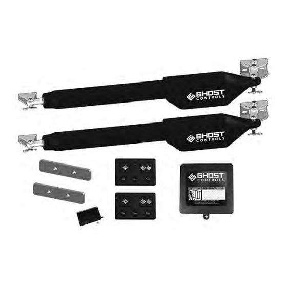
Page 16: Included Parts
P A R T S I N C L U D E D INCLUDED PARTS IN KIT PARTS FOR 1ST OPERATOR Post and Rear Mount Hardware Gate and Front Mount Hardware Gate Mounting Hardware: Front Mounting Hardware: Rear Mounting Hardware: Estate Bracket (Qty 1) GBR6AA AC Transformer:... - Page 17 P A R T S I N C L U D E D INCLUDED PARTS IN KIT PARTS FOR 2ND OPERATOR Post and Rear Mount Hardware Gate and Front Mount Hardware Gate Mounting Hardware: Front Mounting Hardware: Rear Mounting Hardware: Estate Bracket (Qty 1) GBR6AA Battery Harness for Deep...
-
Page 18: Pull-To-Open Installation
Operator is not for use on solid panel privacy gates. PULL-TO-OPEN: GATE SWINGS TO OPEN INSIDE PROPERTY The dimensions and step-by-step instructions that follow are for mounting the GHOST CONTROLS Gate Operator in ® a PULL-TO-OPEN installation system to a standard metal tubular-style agricultural gate that swings into property. - Page 19 P U L L - T O - O P E N STEP 2. Post bracket pre-assembly. Insert the M10x1.5x75mm bolt and M10 washer through the hole that is closest to the post on the post bracket. Bolt should then go through first pivot bracket, pivot spacer, second pivot bracket, and exit bottom hole of post bracket as shown below. Fasten a M10 washer and M10 locknut on the end of the bolt.
- Page 20 P U L L - T O - O P E N NOTE For round wooden post installations we recommend notching the wooden post for proper installation of the post bracket. Follow the diagram for proper notching of a round post. 4-3/8"...
- Page 21 P U L L - T O - O P E N STEP 4. Verifying minimum of 4˝ Gate Clearance and finishing rear post mount bracket assembly. If the clearance is less than 4˝, you will need to adjust the pivot brackets so that you have at least 4˝ of clearance, other- wise, you will not have the minimal mechanical advantage needed to move the gate.
- Page 22 P U L L - T O - O P E N STEP 5. Drilling rear post bracket holes and bolting. A . With the post bracket still clamped to post, mark the center of the bracket slots. Remove the bracket. You will need a 7/16˝...
-
Page 23: Control Box And Battery Box Installation
P U L L - T O - O P E N INSTALLING THE CONTROL BOX AND BATTERY BOX* FOR YOUR PULL-TO-OPEN SYSTEM *IF YOU DO NOT HAVE A BATTERY BOX (ABBT2) AND ARE USING A DEEP CYCLE MARINE BATTERY INSTALL THE CONTROL BOX. STEP 7. -
Page 24: Connecting Battery And Battery Harness
P U L L - T O - O P E N CONNECTING THE BATTERY BOX AND BATTERY HARNESS TO THE CONTROL BOARD STEP 8. Insert battery harness through strain relief in control box and attach to the control board. A . -
Page 25: Connecting Arm To Control Box
P U L L - T O - O P E N CONNECTING OPERATOR ARM TO CONTROL BOX STEP 9. Insert the operator cable into the control box. A . Route the operator cable through the same strain relief as the battery harness cable and into the control box. B. -
Page 26: Setup System Controller
P U L L - T O - O P E N PREPARING THE GATE SYSTEM CONTROLLER The gate system control board provides one convenient place to make all of your system connections and to change any settings that you desire to personalize how your automatic gate opener system operates at your home or property. This main board (shown below) is located inside of the control box of your system and will be referred to in detail through the next few sections. - Page 27 DIP Switch # OFF Position (FACTORY SETTING) ON Position Patent-pending SafeForce® Mode Monitored Safety Mode: Monitored safety devices required / (Factory Default): Force output is Compatible GHOST CONTROLS safety devices only. ® limited to ensure safe operation as Monitored safety devices must be present and operate prop- specified by Type C in UL325 erly as specified by Type B1 or B2 in UL325 requirement.
- Page 28 P U L L - T O - O P E N TURN CONTROL BOX ON. YOU SHOULD HEAR A SERIES OF BEEPS AS THE SYSTEM IS TURNED ON STEP 11. Locate the jog buttons at the top right of control box and press the jog close button to test the arm and connections.
-
Page 29: Front Mount Gate Bracket Installation
P U L L - T O - O P E N FRONT MOUNT GATE BRACKET INSTALLATION WARNING DO NOT SCREW THE OPERATOR ARM IN OR OUT TO ADJUST YOUR GATE OPEN POSITION. DOING SO CAUSES THE SYSTEM TO NOT FUNCTION PROPERLY. TURN THE CONTROL BOX OFF STEP 13. - Page 30 P U L L - T O - O P E N STEP 14. ATTACH THE ESTATE BRACKET AND FRONT MOUNT TO THE GATE. The gate must remain in the desired open position. GATE NEEDS TO BE PLACED IN THE DESIRED OPEN POSITION (this will be the position that your gate will open to) A .
- Page 31 P U L L - T O - O P E N B. Install the front mount gate bracket and estate bracket on the gate by aligning the outermost hole of both brackets and inserting (1) M8 x 65mm flat washer, and (1) M8 nylon locknut through both the estate and front mount bracket, as show below.
- Page 32 P U L L - T O - O P E N F. Align the innermost hole of the estate and front mount brackets and insert (1) M8 x 65mm flat washer, and (1) M8 nylon locknut through both holes and tighten to secure the bracket to the gate. YOUR FRONT MOUNT AND ESTATE BRACKET SHOULD NOW BE ATTACHED AND SECURED TO THE GATE.
-
Page 33: Programming The Closed Limit
P U L L - T O - O P E N PROGRAMMING THE CLOSED LIMIT: PULL-TO-OPEN This is the most common installation. The CLOSED limit is when the operator is extended and the gate is in the closed position. IMPORTANT ONLY THE OPERATOR ARMS’... -
Page 34: Wiring And Connecting The Ac Transformer
P U L L - T O - O P E N WIRING AND CONNECTING THE AC TRANSFORMER NOTE DO NOT USE THE AC TRANSFORMER AND SOLAR POWER AT THE SAME TIME! NOTE TO COMPLETE STEP 18 YOU WILL NEED 16 GAUGE STRANDED, 2-CONDUCTOR LOW VOLTAGE WIRE. CAN EXTEND AC TRANSFORMER UP TO 1,000 FT FROM THE GATE. -
Page 35: Connecting The System With Solar
The panels should be placed within 100 feet of the gate and receive a minimum of 8 hours of direct sunlight per day. UP TO 3 (AXDP) 10-WATT SOLAR PANELS OR THE AX30 30-WATT SOLAR POWER CAN BE CONNECTED TO ANY GHOST CONTROLS SYSTEM CONTROL BOARD. -
Page 36: Setting The Auto Close Feature
P U L L - T O - O P E N SETTING AUTOCLOSE TIME ON YOUR GATE The AUTOCLOSE TIME setting determines how long the gate will remain open each time it operates before automatically closing. The factory default setting is off which requires the user to push either a remote transmitter button, keypad code, or push-button to close the gate. - Page 37 P U L L - T O - O P E N CANCELLING AUTOCLOSE TIME ON YOUR GATE NOTE Canceling AUTOCLOSE can only be performed when the gate opener is idle. Cancelling AUTOCLOSE will remove your previous duration setting and force you to pick a new duration the next time you enable AUTOCLOSE.
-
Page 38: Push-To-Open Installation
Operator is not for use on solid panel privacy gates. PUSH-TO-OPEN: GATE SWINGS TO OPEN OUTSIDE PROPERTY The dimensions and step-by-step instructions that follow are for mounting the GHOST CONTROLS Gate Operator ® PUSH-TO-OPEN installation system to a standard metal tubular-style agricultural fence that swings into property. You will need to make sure you purchase the Push-To-Open Bracket Kit (AXPO) before you start installing. - Page 39 P U S H - T O - O P E N STEP 2. Post bracket pre-assembly. YOU WILL NEED TO MAKE SURE YOU PURCHASE TWO (2) SETS OF THE PUSH-TO-OPEN BRACKET KITS (AXPO) BEFORE YOU START THIS STEP Insert the M10x1.5x75mm bolt and M10 washer through the hole that is closest to the post on the post bracket. Bolt should then go through first push-to-open bracket, pivot spacer, second push-to-open bracket, and exit bottom hole of post bracket as shown.
- Page 40 P U S H - T O - O P E N NOTE For round wooden post installations we recommend notching the wooden post for proper installation of the post bracket. Follow the diagram below for proper notching of a round post. 4-3/8"...
- Page 41 P U S H - T O - O P E N STEP 4. Verifying minimum of 4˝ gate clearance and finishing rear post mount bracket assembly. If the clearance is less than 4˝, you will need to adjust the push-to-open brackets so that you have at least 4˝ of clearance, otherwise, you will not have the minimal mechanical advantage needed to move the gate.
- Page 42 P U S H - T O - O P E N STEP 5. Drilling rear post bracket holes and bolting. A . With the post bracket still clamped to post, mark the center of the bracket slots. Remove the bracket. You will need a 7/16˝...
-
Page 43: Control Box And Battery Box Installation
P U S H - T O - O P E N INSTALLING THE CONTROL BOX AND BATTERY BOX* FOR YOUR PUSH-TO-OPEN SYSTEM *IF YOU DO NOT HAVE A BATTERY BOX (ABBT2) AND ARE USING A DEEP CYCLE MARINE BATTERY INSTALL THE CONTROL BOX. STEP 7. -
Page 44: Connecting Battery And Battery
P U S H - T O - O P E N CONNECTING THE BATTERY BOX AND BATTERY HARNESS TO THE CONTROL BOARD STEP 8. Insert battery harness through strain relief in control box and attach to the control board. A . -
Page 45: Connecting Arm To Control Box
P U S H - T O - O P E N CONNECTING OPERATOR ARM TO CONTROL BOX STEP 9. Insert the operator cable into the control box. A . Route the operator cable through the same strain relief as the battery harness cable and into the control box. B. -
Page 46: Setup System Controller
P U S H - T O - O P E N PREPARING THE GATE SYSTEM CONTROLLER The gate system control board provides one convenient place to make all of your system connections and to change any settings that you desire to personalize how your automatic gate opener system operates at your home or property. This main board (shown below) is located inside of the control box of your system and will be referred to in detail through the next few sections. - Page 47 DIP Switch # OFF Position (FACTORY SETTING) ON Position Patent-pending SafeForce® Mode Monitored Safety Mode: Monitored safety devices required / (Factory Default): Force output Compatible GHOST CONTROLS safety devices only. ® is limited to ensure safe opera- Monitored safety devices must be present and operate prop- tion as specified by Type C in UL325 erly as specified by Type B1 or B2 in UL325 requirement.
- Page 48 P U S H - T O - O P E N TURN CONTROL BOX ON. YOU SHOULD HEAR A SERIES OF BEEPS AS THE SYSTEM IS TURNED ON STEP 11. Locate the jog buttons at the top right of control box and press the jog open button to test the arm and connections.
-
Page 49: Front Mount Gate Bracket Installation
P U S H - T O - O P E N FRONT MOUNT GATE BRACKET INSTALLATION WARNING DO NOT SCREW THE OPERATOR ARM IN OR OUT TO ADJUST YOUR GATE OPEN POSITION. DOING SO CAUSES THE SYSTEM TO NOT FUNCTION PROPERLY. TURN THE CONTROL BOX OFF STEP 13. - Page 50 P U S H - T O - O P E N STEP 14. MOUNTING THE ESTATE BRACKET AND FRONT MOUNT TO THE GATE. The gate must remain in the desired closed position GATE NEEDS TO BE IN THE DESIRED CLOSED POSITION (this will be the position that your gate will close to) A .
- Page 51 P U S H - T O - O P E N B. Install the front mount gate bracket and estate bracket on the gate by aligning the outermost hole and inserting (1) M8 x 65mm flat washer, and (1) M8 nylon locknut through gate and front mount bracket, MAKE SURE GATE IS STILL IN CLOSED as show below.
- Page 52 P U S H - T O - O P E N F. Align the innermost hole of the estate and front mount brackets and insert (1) M8 x 65mm flat washer, and (1) M8 nylon locknut through both holes and tighten to secure the bracket to the gate. YOUR FRONT MOUNT AND ESTATE BRACKET SHOULD NOW BE ATTACHED AND SECURED TO THE GATE.
-
Page 53: Programming The Open Limit
P U S H - T O - O P E N PROGRAMMING THE OPEN LIMIT: PUSH-TO-OPEN The OPEN limit is when the operator is extended and the gate is in the closed position. IMPORTANT ONLY THE OPERATOR ARMS’ EXTENDED LIMIT IS ADJUSTABLE AND CAN BE SET WITH THE CONTROL BOARD. -
Page 54: Wiring And Connecting The Ac Transformer
P U S H - T O - O P E N WIRING AND CONNECTING THE AC TRANSFORMER NOTE DO NOT USE THE AC TRANSFORMER AND SOLAR POWER AT THE SAME TIME! NOTE TO COMPLETE STEP 18 YOU WILL NEED 16 GAUGE STRANDED, 2-CONDUCTOR LOW VOLTAGE WIRE. CAN EXTEND AC TRANSFORMER UP TO 1,000 FT FROM THE GATE. -
Page 55: Connecting The System With Solar
The panels should be placed within 100 feet of the gate and receive a minimum of 8 hours of direct sunlight per day. UP TO 3 (AXDP) 10-WATT SOLAR PANELS OR THE AX30 30-WATT SOLAR POWER CAN BE CONNECTED TO ANY GHOST CONTROLS SYSTEM CONTROL BOARD. -
Page 56: Setting The Auto Close Feature
P U S H - T O - O P E N SETTING AUTOCLOSE TIME ON YOUR GATE The AUTOCLOSE TIME setting determines how long the gate will remain open each time it operates before automatically closing. The factory default setting is off which requires the user to push either a remote transmitter button, keypad code, or push-button to close the gate. - Page 57 P U S H - T O - O P E N CANCELLING AUTOCLOSE TIME ON YOUR GATE NOTE Canceling AUTOCLOSE can only be performed when the gate opener is idle. Cancelling AUTOCLOSE will remove your previous duration setting and force you to pick a new duration the next time you enable AUTOCLOSE.
-
Page 58: Troubleshooting
T R O U B L E S H O O T I N G TROUBLESHOOTING GUIDE For troubleshooting help visit: https://ghostcontrols.com/pages/technical-support For helpful videos visit: https://ghostcontrols.com/pages/installation-video. LEARN NEW REMOTE 2021-09 DO NOT USE this procedure if you already have a remote that operates the gate and just want to add an additional remote. If you want to add an additional remote to your system, please refer to the remote manual or ghostcontrols.com. - Page 59 T R O U B L E S H O O T I N G I PRESS MY TRANSMITTER AND NOTHING HAPPENS (NO BEEPS/NO MOVEMENT) The Number 3 dip switch (blue box of 4 switches on your system control board) is in the wrong position. It must be posi- tioned to the left.
-
Page 60: Connecting Optional Accessories
INACTIVE — Opens circuit or has no connection. ACTIVE — Input is shorted to COM or BATTERY NEGATIVE. CYCLE INPUT (CYC): Use this terminal for Ghost Controls Push Button (AXPB). © G h o s t C o n t r o l s 2 0 2 2 ®... - Page 61 OPEN > STOP > CLOSE > STOP > OPEN >... OPEN INPUT (OPEN): Use this terminal for Ghost Controls Vehicle Detector (AXXV). Active — OPENS gate to full open limit and prevents it from closing.
- Page 62 B L A N K © G h o s t C o n t r o l s 2 0 2 2 ®...
-
Page 63: Manual Gate Operation
M A N U A L MANUAL GATE OPERATION EVERY USER MUST KNOW THESE STEPS The gate can be opened or closed manually by releasing the front mount from the gate. You must disconnect the operator only after the operator power switch is OFF and the gate is NOT moving. If you have the accessory ZombieLock installed, this lock should be manually disengaged with the key because removing power does not ®... -
Page 64: Accessories
® a new remote to an existing system. CR2032 Battery Included. STANDARD REMOTE TRANSMITTER | AXS1 The standard remote transmitter will control up to two separate GHOST CONTROLS gate systems ® (single or dual) and it can be learned as a new remote to an existing system. CR2032 Battery Included. - Page 65 , or any other device that needs to be attached to tubes. ® WIRED VEHICLE SENSOR | AXXV The GHOST CONTROLS Vehicle Sensor is the easiest way to trigger your gate to open when a vehicle ® is trying to exit your property. This sensor is buried beneath the ground surface next to your driveway and connects into your gate controller box.
Need help?
Do you have a question about the HDP2 and is the answer not in the manual?
Questions and answers