Table of Contents
Advertisement
Quick Links
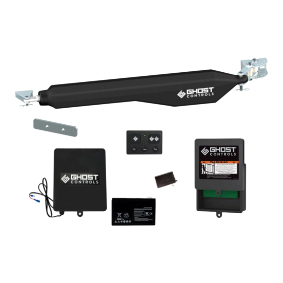
Quickstart Guide for DS1U & DTP1 Single and DD2U & DEP2 Dual Automatic Gate Opener Kits
This installation overview shows the most common installation
of a single, pull to open application and is intended for use as
a guide once you have read and understand the complete
installation manual. Please refer to the installation manual for
safety information prior to installing your automatic gate opener.
The installation manual is required for information on additional
features, programming, dual applications, and push to open
applications.
A complete installation video can be viewed at:
ghostcontrols.com/support/installation-video
A
C
D
E
3. Align the center of the post pivot bracket over your
established center line and clamp the bracket to the hinge
post.
DRAWING SHEET TITLE
7. Determine the mounting location for the control box
making sure the arm power cable will reach. Pre-drill the
UNLESS OTHERWISE SPECIFIED:
control box mounting holes with a 7/32" drill bit and mount
A
C
D
using the screws provided with the control box.
PART
DWG
C
D
E
A
PREPARE THE GATE
Post must be a minimum of 6"x 6" wood or 3" steel
and set in concrete. Gate must be plumb, level, and
swing freely. Wheels cannot be used and ball bear-
ing hinges are recommended for gates weighing over
200 lbs. Operator is not for use on solid panel gates.
A
A
C
D
E
C
D
F
G
H
4. Adjust the post bracket and pivot brackets as needed
to achieve a minimum of 4" clearance between the hole in
DRAWING SHEET TITLE
the pivot brackets and the inside of the gate in the desired
open position. Add the 2nd pivot bracket bolt and tighten
UNLESS OTHERWISE SPECIFIED:
both.
A
C
D
E
A
>4.0
8. Insert the battery harness through the strain relief and
attach to the control board, then attach the other end to
your battery. ABBT Battery Box Kit not shown here.
DRAWN ON
SHEET SCALE
A
E
F
A
G
H
C
D
DRAWING SHEET TITLE
F
G
H
UNLESS OTHERWISE SPECIFIED:
C
D
A
DRAWING SHEET TITLE
UNLESS OTHERWISE SPECIFIED:
1. Operator should be mounted as close to the center of
the gate as possible. Determine the mounting location of
A
C
the operator and mark the center line on the gate hinge
post.
C
D
F
G
H
E
F
G
5. Mark the bolt holes and drill using a 7/16" drill bit.
Install the 4 mounting bolts and tighten.
UNLESS OTHERWISE SPECIFIED:
DRAWN ON
SHEET SCALE
A
PART
DWG
F
G
H
A
C
C
D
9. Insert the arm cable through the strain relief and attach
using the screw terminals on the control board. Make the
screw terminal connections are tight and are contacting
E
F
G
H
the wire and not the wire insulation. Tighten strain relief.
DRAWN ON
UNLESS OTHERWISE SPECIFIED:
PART
DWG
E
F
G
C
D
DRAWN ON
SHEET SCALE
2. Pre-assemble the post pivot bracket as shown. Do not
completely tighten at this point..
D
E
F
G
H
A
E
F
6
5
H
4
A
3
2
DRAWING FILE NAME
QS030 Bracket Pre-assembly
PART/ASSEMBLY FILE NAME
PBR6AA Post Mount Bracket Assem
6. Install the rear of the operator using the clevis pin,
1
bushing, and hairclip as shown.
DRAWING SHEET TITLE
A
DRAWN ON
SHEET SCALE
A
PART
DWG
D
E
F
G
H
E
F
G
10. Verify that the dip switches are set to the correct
position as shown.
DIP #
DRAWING SHEET TITLE
1
A
2
SHEET SCALE
A
H
3
PART
DWG
E
F
4
B
C
D
E
F
G
H
G
H
Exploded
Assembled
C
D
E
PART/ASSEMBLY NUMBER
PART/ASSEMBLY DESCRIPTION
DRAWING SHEET TITLE
Sheet1
PART/ASSEMBLY CONFIGURATION NAME
QS030 Pre-assembly
MATERIAL(S)
UNLESS OTHERWISE SPECIFIED:
LENGTH DIMENSIONS PROVIDED ARE IN MILLIMETERS (mm)
LENGTH DUAL DIMENSIONS ARE IN INCHES (in)
ANGULAR DIMENSIONS PROVIDED ARE IN DEGREES ( )
REVISION
DRAWN BY
DRAWN ON
SHEET SCALE
SHEET SIZE
CAY
NUMBERS
2018Apr13
1:2
THE INFORMATION CONTAINED IN THIS DRAWING IS THE SOLE
PART DWG
PROPERTY OF GHOST CONTROLS, LLC. ANY REPRODUCTION IN
PART OR AS A WHOLE WITHOUT THE WRITTEN PERMISSION OF
1
DWG REVISOR
CAY
REVISED ON
2018May17
PAGE NUMBER
1 of 1
GHOST CONTROLS, LLC. IS PROHIBITED. DESIGNS, PRODUCTS,
AND DRAWINGS ARE SUBJECT TO CHANGE WITHOUT NOTICE.
B
C
D
E
F
G
H
H
DRAWING SHEET TITLE
UNLESS OTHERWISE SPECIFIED:
OFF Position
ON Position
PART
Factory Default:
Push-To-Open
Pull-To-Open
C
D
E
Factory Default:
Warning Disabled
Warning Enabled
Monitored
DRAWN ON
SHEET SCALE
Factory Default:
A
External Safety
SafeForce
®
Mode
Devices Mode
Factory Default:
G
H
Simultaneous
Delay Open 2nd
Open
Arm
6
5
4
F
3
2
1
A
DWG
F
Advertisement
Table of Contents

Related Manuals for Ghost Controls DS1U


Summary of Contents for Ghost Controls DS1U
- Page 1 Quickstart Guide for DS1U & DTP1 Single and DD2U & DEP2 Dual Automatic Gate Opener Kits This installation overview shows the most common installation PREPARE THE GATE 1. Operator should be mounted as close to the center of 2. Pre-assemble the post pivot bracket as shown. Do not of a single, pull to open application and is intended for use as Post must be a minimum of 6"x 6"...
- Page 2 1:60 NUMBERS THE INFORMATION CONTAINED IN THIS DRAWING IS THE SOLE LENGTH DIMENSIONS PROVIDED ARE IN MILLIMETERS (mm) PROPERTY OF GHOST CONTROLS, LLC. ANY REPRODUCTION IN PART DWG LENGTH DUAL DIMENSIONS ARE IN INCHES (in) UNLESS OTHERWISE SPECIFIED: open position.
Need help?
Do you have a question about the DS1U and is the answer not in the manual?
Questions and answers