Advertisement
Quick Links
Advertisement

Subscribe to Our Youtube Channel
Related Manuals for Keysight Technologies i7090


Summary of Contents for Keysight Technologies i7090
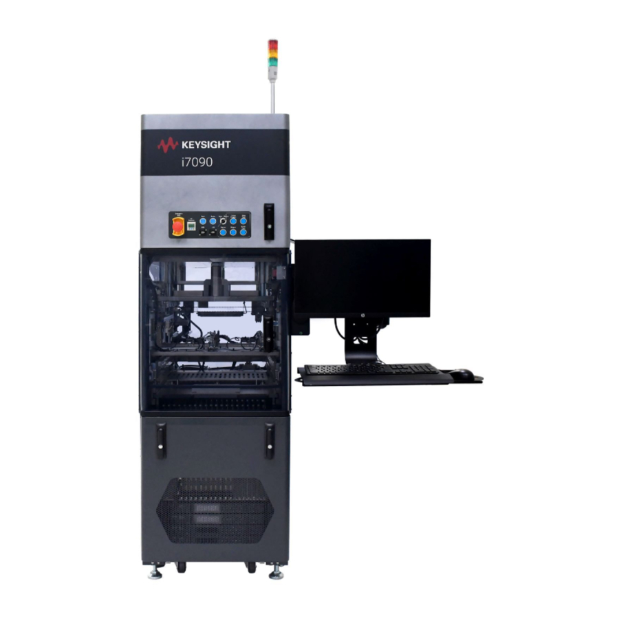
- Page 1 Site Preparation Keysight i7090 Board Test System...
- Page 2 Keysight Technologies as governed by U.S. Government Rights could result in personal injury or death. United States and international The Software is "commercial computer...
-
Page 3: Table Of Contents
SMEMA Communication The Importance of Site Preparation The Keysight i7090 board test system is a complex and sophisticated automatic test equipment. To ensure that your site is properly equipped for your new system, and to minimize the possibility of problems or delays in system installation, read and follow the recommendations provided in this manual. -
Page 4: Safety Notices
If the equipment is used in a manner not specified by the manufacturer, the equipment protection may be impaired. The i7090 system is designed for indoor use and in an area with low condensation. Clean with slightly dampened cloth Clean the outside of the equipment with a soft, lint-free, slightly dampened cloth. -
Page 5: Equipment Rating
Equipment Rating Equipment Rating • Pollution degree 2 • Installation category II • Altitude: Up to 2000 m • Humidity: 50% to 80% • Electrical supply: 208 Vac or 415 Vac, 50/60Hz, 16 A, 3 phase ° ° • System Operating Temperature: 0 C to 40 •... -
Page 6: Site Preparation Process
Site Preparation Process Site Preparation Process Successful system preparation and installation requires planning and effort by both you and Keysight. Following are summaries of each party’s responsibilities. Keysight’s Responsibilities As a part of the purchase of a Keysight board test system, Keysight will provide the following: •... - Page 7 • Proper use of the system — You are responsible for ensuring that use of the system is consistent with local laws and regulations. • Receiving the system • You should remove the crate from the i7090 system, but not remove the system from the pallet. See Moving Access Requirements for the space requirements.
- Page 8 You should move the system to the site where it will be installed, or a safe storage area. The Keysight representative will remove the i7090 system from the pallet. You may leave the smaller boxes for the Keysight representative to unpack when the system is installed.
-
Page 9: Structural Requirements
Structural Requirements Structural Requirements i7090 System Dimensions Floor Space Requirements Moving Access Requirements i7090 System Dimensions Figure 1 Dimensions 631 mm (25 in) 522 mm (21 in) 1543 mm (61 in) 545 mm (22 in) 1875 mm (74 in) 433 mm (17 in) - Page 10 Structural Requirements Floor Space Requirements The floor plan in Figure 2 incorporates areas needed around the i7090 system to access panels and connection points for devices. Figure 2 Recommended clearance Recommended clearance 1000 mm (40 in) i7090 System 1543 mm (61 in)
- Page 11 Structural Requirements Moving Access Requirements The i7090 system will be crated for delivery. The dimensions and weights are as follows: i7090 system 600 mm x 1500 mm x 1950 mm (width x length x height) Crate 1219 mm x 2140 mm x 2274 mm (width x length x height)
-
Page 12: Power Requirements
Power Requirements Power Requirements It is the customer’s responsibility to prepare the site with adequate AC power for the system as described in this section. The system power line is wired differently for different power configurations. The voltage of the system is marked on the rear panel of the system. If you will be installing the system in a location in which the actual power does not match the power configuration, you may need to rewire the outlet connections in the electrical panel (see... - Page 13 Power Requirements Figure 3 Wiring diagram Electrician must determine the conductor size i7090 System Main Switch Circuit breaker on factory side Power receptacle and power cord from inline handler Power Drop • A dedicated power drop must be provided for the system due to its high current requirements.
- Page 14 Power Requirements Sizing the Input Wires and Circuit Breakers Table 1 Power requirements Power Frequency Voltage Full-Load Option line-to-neut / Amps (FLA) line-to-line 208 V 3-Phase Delta 50/60 Hz 16 A 16 A N (optional) 16 A 16 A 208 V 3-Phase Wye 50/60 Hz 16 A 16 A...
- Page 15 Power Requirements Power Cord The power cord to the i7090 system depends on the country where the system will be installed: • International: Uses 5-conductor cord with IEC 60309 plug (Altech K51S30A or equivalent) and mating receptacle. • North America: Uses #12 AWG 5-conductor cord with NEMA plug that mates with NEMA L21- 20.
- Page 16 North America 3-phase systems AC Voltage Source 2.8 m (8.2 ft) of #12 AWG 5-conductor SO cord. Cord and male receptable supplied by Keysight. 3-phase circuit breaker i7090 System Power cord with female receptacle supplied by customer Main Switch Conductors and service sized...
- Page 17 Power Requirements Is Electrical Re-wiring Necessary? Re-wiring the system is necessary only if you are connecting it to a different power configuration than it was wired for, not merely a different voltage. Delta (3PD) and Wye (3PY) are equivalent configurations. Table 2 and the examples below.
- Page 18 Power Requirements Electrical Wiring Diagrams Note that the system power phase configuration is determined by the location of the jumper, as shown in the wiring diagrams. Figure 7 Wiring diagram for 415 V input; 3-phase wye with neutral Figure 8 Wiring diagram for 208 V;...
-
Page 19: Compressed Air Requirements
Compressed Air Requirements Compressed Air Requirements The i7090 system uses compressed air to pressurize air cylinders that actuate the fixture drawer and fixture pull-down towers. The pull-down towers pull and hold a fixture down onto the testhead, enabling contact between the pins on the fixture and the spring-loaded interface pins in the test engine. -
Page 20: Smema Communication
The communication interface between adjacent machines is provided by a SMEMA- compliant protocol, allowing the i7090 system to integrate directly into printed circuit assembly manufacturing process. 14 way AMP sockets are provided at the rear of the i7090 system to connect to the upstream and downstream systems (Figure 10). - Page 21 Upstream System Ready Output signal to upstream system. i7090 system forces this signal to low when it is ready to receive a board. Downstream System Busy Input signal to i7090 system.
- Page 22 1 Upstream system closes UBA relay to indicate to i7090 system that a board is available for testing. 2 After a delay of 500 ms, i7090 system closes USB relay to indicate to upstream system that it is ready to receive the board.
- Page 23 Site Prep Checklist Task Checklist Site Planning Location chosen? Specialists assigned? Site Coordinator: ___________________________________________________________________________ System Administrator: ___________________________________________________________________________ Structural Specialist: ___________________________________________________________________________ EMC Specialist: ___________________________________________________________________________ Environmental Specialist: ___________________________________________________________________________ Electrical Specialist: ___________________________________________________________________________ Compressed Air Specialist: ___________________________________________________________________________ Communications Specialist: ___________________________________________________________________________ ...
- Page 24 Task Checklist Power Requirements System Power What power option is your system? Opt. _______________ AC mains power verified? Mains disconnect installed? Do you need to install power conditioning equipment? Do you need to install a new transformer? ...
- Page 26 This information is subject to change without notice. © 2021 Keysight Technologies Edition 1, January 2021 www.keysight.com...
Need help?
Do you have a question about the i7090 and is the answer not in the manual?
Questions and answers