
Related Manuals for ARC MJLT-2005


Summary of Contents for ARC MJLT-2005
-
Page 1: Table Of Contents
Issue date: 29/7/2021 SHUTTER REMOTE CONTROL & RECEIVER MODULE MJLT-2005+MJLR-2001 CONTENTS 1. Overview and features Page 2. 2. Diagrams Page 3. 3. Battery Page 4. 4. Mounting on surface Page 6. 5. Installation wiring Page 7. 6. Pairing / Un-pairing device Page 10. -
Page 2: Overview And Features
Issue date: 29/7/2021 1. Overview and features From shutters to pavilions, motorized electronics and furnishing are part of a modern home. Now they can be part of your connected home. 2-in-1 handy remote or wall switch control can easily be wall mounted and or affix on any magnetic base. -
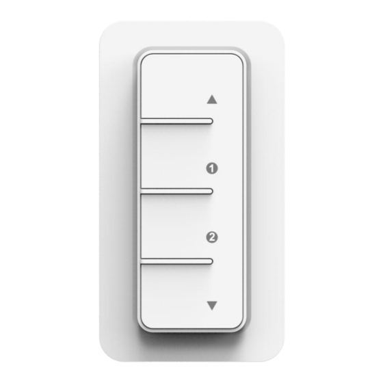
Page 3: Diagrams
Issue date: 29/7/2021 2. Diagrams. Main Handy Remote Control Red LED On / Up Scene 1 / 2 Off / Down Magnetic Back Holder Front Back Fixing Screws Receiver Module DIAGRAMS... -
Page 4: Battery
Issue date: 29/7/2021 3. Battery 1. With a Φ3mm flat headed screwdriver, insert into the allocated slot and with a little force push open the battery cover then remove battery insulation stirp. (First time use only) 2. Insert flat headed screwdriver and slightly lift to remove battery. BATTERY... - Page 5 Issue date: 29/7/2021 3. Insert new 3V CR2032 battery making sure the positive symbol is facing upwards and slide back the battery cover. LITHIUM BATTERY CAUTION: Risk of Explosion if battery is replaced by an incorrect type. Dispose of used batteries according to the environment protection rules.
-
Page 6: Mounting On Surface
Issue date: 29/7/2021 4. Mounting On Surface 1. Insert flat headed screwdriver into the button slot and lift open the front magnetic holder. 2. Position the back magnetic holder onto surface making sure the arrow is facing up then affix tightly with 2 screws. 3. -
Page 7: Installation Wiring
Issue date: 29/7/2021 5. Installation – Wiring To install module into wall box, break off the mounting tabs. IRING Cut off main power before installing and wiring. ⚫ Strip wires at least 7mm then connect the wires as per diagrams below, ensure terminals are properly tightened and no bare wire is visible. - Page 8 Issue date: 29/7/2021 With 230V Motor 1. Connect permanent Live wire into module terminal [L]. 2. Connect Neutral wire into module terminal [N]. 3. Connect jump wire in between module terminal [Com] and [L]. 4. Connect 2 Live wire from motor into module terminal [ ], one to control ‘Up’...
- Page 9 Issue date: 29/7/2021 With 24V Motor 1. Connect permanent Live wire into module terminal [L]. 2. Connect Neutral wire into module terminal [N]. 3. Connect 2 Live wire (A+ & B+) from motor into module terminal [ ], one to control ‘Up’...
-
Page 10: Pairing / Un-Pairing Device
Issue date: 29/7/2021 6. Pairing / Un-pairing Device AIRING Pairing using LEARNING MODE: 1. On the module receiver, press ‘Learn’ button once (Left LED on module will flash), this will enter learning mode. 2. Within 6 seconds press the UP button to pair, left LED will quick flash to confirm that pairing is successful and complete. -
Page 11: Motor Calibration
Issue date: 29/7/2021 7. Motor Calibration There are wide variety of shutters, curtains, and motorised electronics in the market. So, for a better performance the receiver module has a calibration features built in. For the shutter to position properly, we must firstly set up the maximum and minimum level of the actual shutter you wish to control. - Page 12 Issue date: 29/7/2021 Set up with MJLT-2005 1. On the receiver module press SET button for 3 seconds, both LED on module will flash. 2. With the remote press DOWN button once to close the shutter and once it reaches to the bottom, press the DOWN ...
-
Page 13: Operation
Issue date: 29/7/2021 8. Operation LOSE PERATION MJLT-2005 Method 1. Press the UP button to open shutter. To stop, press the UP button again. Press the DOWN button to close shutter. To stop, press the DOWN button again. - Page 14 Issue date: 29/7/2021 CENE ETUP Scene setup and control is only compatible with M Series receiver(s). 1. Using the button set the desired shutter level position, for example halfway down. 2. Press button 1 or 2 for 3 seconds to store the scene, LED will quick flash to confirm scene is successful stored.
- Page 15 Issue date: 29/7/2021 MJLR-2001 module receiver is also compatible to MEBT-2004, MRYT-1805, MTHT-1806, MEBT-1706 and MKFT-1704. NDIVIDUAL PERATION MEBT-2004 Pair MEBT-2004 with MJLR-2001 module first by entering learning mode and press MEBT-2004 button once. Operation: Method 1. Press button once to open shutter. While the shutter is opening press the button once to stop.
- Page 16 Issue date: 29/7/2021 Operation: Slide function switch to II position. Method 1. Turn rotary button clockwise to open shutter, the shutter will stop after you stop turning the rotary button. Turn rotary button counterclockwise to close shutter, the shutter will stop after you stop turning the rotary button.
- Page 17 The next time the button is pressed, the shutter will run at the opposite position. Scene Control. If you already used MJLT-2005 to set up scene, you can also control scene 1 and 2 with this remote control. Slide the function switch to 2 position Scene 1.
- Page 18 The next time the button is pressed, the shutter will run at the opposite position. Scene Control. If you already used MJLT-2005 to set up scene, you can also control scene 1 and 2 with this remote control. Slide the function switch to 2 position Scene 1.
- Page 19 The next time the button is pressed, the shutter will run at the opposite position. Scene Control. If you already used MJLT-2005 to set up scene, you can also control scene 1 and 2 with this remote control. Slide the function switch to 2 position Scene 1.
-
Page 20: Specifications
Its complaisance with the European Directives Which apply to the product and in particular its compliance with the harmonizes standards and specifications. Dimension MJLT-2005: 60 x 110 x 15 mm MJLR-2001: 48 x 48 x 25mm Weight: MJLT-2005: 60g MJLR-2001: 40g Accessory pack enclosed: 2pcs double sided adhesive tape.
Need help?
Do you have a question about the MJLT-2005 and is the answer not in the manual?
Questions and answers