Table of Contents
Advertisement
Quick Links
Advertisement
Table of Contents

Related Manuals for ARC Flex Series


Summary of Contents for ARC Flex Series
- Page 1 FLEX8ES User’s Manual FCC Version...
-
Page 2: Table Of Contents
Table of Contents Page Introduction Radio Controlled Safety General System Information Transmitter Handset External Illustration (Standard Push Button Configuration) Internal Illustration Receiver Unit External Illustration Internal Illustration Function Settings Transmitter Handset System Channel Settings Push Button Functions with LED Displays Standard Push Button Configuration (Transmitter Toggle) Standard Push Button Configuration (A/B Selector) Inline Push Button Configuration (Transmitter Toggle) - Page 3 Dip-switch Settings Interlocked Functions Non-interlocked Functions Jumpers Settings I-Chip Programming Port Voltage Settings System Channels Table Receiver Installation Output Relay Contact Diagram Pre-Installation Precautions Step-By-Step Installation 26~27 System Testing Operating Procedure Transmitter Operation General Operating Procedure 28~29 A/B Selector Push Button Operating Procedure Pitch &...
-
Page 4: Introduction
1. Introduction The FLEX radio remote control systems are designed for control of industrial equipment and machinery such as overhead traveling cranes, jib cranes, gantry cranes, tower cranes, electric hoists, winches, monorails, conveyor belts, mining equipment and other material handling equipment where wireless control is preferred. Each FLEX system consists of a transmitter handset and receiver unit. -
Page 5: Radio Controlled Safety
2. Radio Controlled Safety Flex radio remote control system should be operated by persons with sufficient amount of knowledge and skill in crane operation and safety. Persons being trained to operate a radio remote controlled crane should possess the knowledge of all hazards peculiar to radio remote controlled crane operation, ability to judge distance and moving objects, equipment capacity and radio remote controlled safety rules. -
Page 6: General System Information
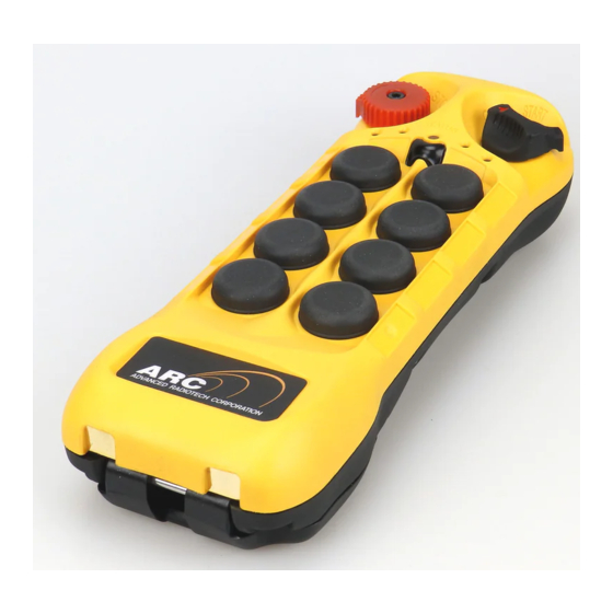
3. General System Information A. TRANSMITTER HANDSET 1. External Illustration (Standard Push Button Configuration) (Fig. 01) (Fig. 02) Emergency Stop Button Push Button #5 Removable Power Key Switch Push Button #7 Push Button #2 Strap Ring Push Button #4 System Information Push Button #6 System Channel Push Button #8... -
Page 7: Internal Illustration
2. Internal Illustration (Fig. 03) (Fig. 04) Encoder Board I-CHIP Arial Antenna Function Dip-Switch Transmitting Module Channel Dip-Switch Status LED Display Battery Contact Mechanism Function LED Displays Page 6... -
Page 8: Receiver Unit
B. RECEIVER UNIT 1. External Illustration (Fig. 05) Shock Mount COM LED Display External Antenna Jack Output Contact Diagram Power LED Display System Information Status LED Display Cord Grip SQ LED Display Page 7... -
Page 9: Internal Illustration
2. Internal Illustration (Fig. 06) AC Line Filter Decoder Module Power Transformer Output Relay Board Receiving Module Page 8... -
Page 10: Function Settings
4. Function Settings A. TRANSMITTER HANDSET 1. System Channel Settings CHANNEL (Fig. 07) Set the transmitter channel by adjusting the channel dip-switch located on the backside of the transmitter encoder board (refer to Fig. 07 above). Only the first six (6) positions are used for channel programming (refer to Fig. -
Page 11: Push Button Functions With Led Displays
2. Push Button Functions with LED Displays A. Standard Push Button Configuration (Transmitter Toggle) Set transmitter toggle (latching output relay) function by adjusting the 8-position function dip-switch located on the backside of the transmitter encoder board (refer to Fig. 09 below). The LED 1 through LED 4 shown inside the shaded box (see below) illustrates which LED on the transmitter will light up when the designated push button (PB5 ~ PB8) is pressed. -
Page 12: Standard Push Button Configuration (A/B Selector)
B. Standard Push Button Configuration (A/B Selector) There are four (4) different types of A/B selector sequence available on the Flex system. Choose the one that is most suitable for your application. Type-A selector sequence A → B → A → B … Type-B selector sequence Off →... -
Page 13: Inline Push Button Configuration (Transmitter Toggle)
C. Inline Push Button Configuration (Transmitter Toggle) The push button arrangement for inline push button setup starts from top to bottom and then from right column to left column (refer to Fig. 10 below). To set inline push button configuration please refer to JP4 and JP5 jumpers setting on page 22. With inline push buttons configuration, PB1 &... -
Page 14: Inline Push Button Configuration (A/B Selector)
D. Inline Push Button Configuration (A/B Selector) There are four (4) different types of A/B selector sequence available on the Flex system. Choose the one that is most suitable for your application. Type-A selector sequence A → B → A → B … Type-B selector sequence Off →... -
Page 15: Channel Change Via Push Buttons
3. Channel Change via Push Buttons Other than CHANNEL dip-switch on the encoder board, the transmitter channel can also be changed directly on the push buttons. Please refer to the instruction below on how to change transmitter channel via push buttons. Press and hold PB1, PB2 and PB3 and rotate the power key to START position at the same time. -
Page 16: Program 4-Digit Security Code
4. Program 4-digit Security Code Prior to rotating the transmitter power key-switch to START position to begin operation, you must first enter a 4-digit security code in order to proceed further. When this 4-digit security code is input correctly, a green light will appear on the Status LED. Please refer to the instruction below on how to program the 4-digit security code. -
Page 17: I-Chip
5. I-Chip I-CHIP functioned in a way that is very similar to a SIM card inside a mobile phone, which stores information such as your phone number, account number, phone book and other settings. I-CHIP works exactly the same way, as it stores information such as system serial number/ID code, channel and push button configurations. -
Page 18: Receiver Unit
B. RECEIVER UNIT 1. System Channel Settings (Fig. 12) Even though Flex system is equipped with automatic channel scanning receiver, the user can also set the receiver channel manually. Please refer to page 30 on how automatic channel scanning receiver works. -
Page 19: Auxiliary Functions
2. Auxiliary Functions a. ON/OFF Push Button Function The user can set any of the two adjacent push buttons on the transmitter to behave like a mechanical ON & OFF rocker switch (refer to page 20 on how to set to this function). When “On”... -
Page 20: Toggled Contact
Toggled Contact When push button is released the output relay corresponds to that push button will remained closed (maintained contact) until next time the user presses the same push button again (refer to page 21 on how to set to this function). This type of contact is usually applies to external application such as lights. -
Page 21: Dip-Switch Settings
4. Dip-Switch Settings a. Interlocked Functions Interlocked means the two adjacent push buttons can not be activated simultaneously at the same time as it will cancel each other out. Interlocked settings are usually applied to crane’s forward and reverse motions. Each dip-switch on the decoder module corresponds to one (1) motion or two (2) adjacent push buttons (refer to Fig. -
Page 22: Non-Interlocked Functions
b. Non-Interlocked Functions Contrary to interlocked settings, non-interlocked settings allow the two adjacent push buttons be used simultaneously at the same time. Non-interlocked settings are usually applied to crane’s auxiliary functions such as lights, horn, auxiliary stop and Pitch & Catch. Each dip-switch on the decoder module corresponds to one (1) motion or two (2) adjacent push buttons (left &... -
Page 23: Jumpers Settings
5. Jumper Settings Jumper settings are applied to functions such as mainline-disconnect time, Start function, transmitter push button layout, system information (serial number/ID code) programming and system testing. The jumpers #1 ~ #7 are located on the decoder module above the six (6) dip-switches (refer to Fig.16 below). -
Page 24: I-Chip Programming Port
6. I-Chip Programming Port (Fig. 17) I-CHIP programming port located on the decoder module (refer to Fig. 17 above) inside the receiver is designed for the purpose of transferring system serial number/ID code either from I-CHIP to receiver or from receiver to I-CHIP. If you wish to transfer system information from receiver to I-CHIP, just insert the I-CHIP onto the programming port (JP6 jumper not inserted), wait until the Status LED on the decoder module turned constant green (within 2 seconds), and then take the I-CHIP out of the programming port (programming completed). -
Page 25: System Channels Table
5. System Channels Table Dip-switch Dip-switch Channel Frequency Channel Frequency Setting Setting 433.000MHZ 000000 433.775MHZ 100000 433.000MHZ 000001 433.800MHZ 100001 433.025MHZ 000010 433.825MHZ 100010 433.050MHZ 000011 433.850MHZ 100011 433.075MHZ 000100 433.875MHZ 100100 433.100MHZ 000101 433.900MHZ 100101 433.125MHZ 000110 433.925MHZ 100110 433.150MHZ 000111 433.950MHZ... -
Page 26: Receiver Installation
6. Receiver Installation A. OUTPUT RELAY CONTACT DIAGRAM If the transmitter’s push button #7 is programmed with Select A/B function (refer to page 11 & 13) then “Select A” position shall be connected to “FWD” output relay (wire #19) and “Select B” position connected to “AUX-1”... -
Page 27: Pre-Installation Precautions
B. PRE-INSTALLATION PRECAUTIONS Make sure the transmitter and receiver are with identical serial number/ID code and channel. Make sure the receiver is not set to the same channel as any other systems in use in the surrounding area. Make sure that the crane or equipment is working properly prior to installation. Make sure the power source to the receiver is set correctly. -
Page 28: System Testing
For best reception the location of the receiver should be visible to the operator at all time. The location selected should not be exposed to high levels of electric noise. Mounting the receiver next to an unshielded variable frequency drive may cause minor interference. Always locate the receiver as far away from variable frequency drive as possible. -
Page 29: Operating Procedure
7. Operating Procedure A. TRANSMITTER OPERATION 1. General Operating Procedure Reset the red emergency stop button located on the top left hand side of the transmitter handset by rotating it either clockwise or counter clockwise, the red button will pop up. Turn on the transmitter power by inserting the black-colored key into the power key slot located on the top right hand side of the transmitter handset and rotate it clockwise to “On”... -
Page 30: A/B Selector Push Button Operating Procedure
Now press any push button on the transmitter handset to operate the crane or equipment. In case of an emergency, press down the red emergency stop button will immediately disconnect the receiver mainline (Status LED blinks red). To reset the emergency stop button just rotate the red button either clockwise or counter-clockwise, it will pop up. -
Page 31: Automatic Channel Scanning Operating Procedure
4. Automatic Channel Scanning Operating Procedure After changing transmitter channel (refer to page 9), turn on the transmitter power and rotate the power key switch to “Start” position and hold it there for up to 1.0 minute. Within this 1-minute period the receiver will search (channel 01 ~ channel 62) and lock onto the newly selected transmitter channel automatically. -
Page 32: Status Light Indicators & Warnings
B. STATUS LIGHT INDICATORS & WARNINGS 1. Transmitter STATUS Light Indication Type Display Type Indication (Green & Red) Voltage goes below 1.9V at initial power on - transmitter power shuts off. Constant red Voltage goes below 1.8V during operation - transmitter power shuts off. -
Page 33: Receiver Status Light Indication
2. Receiver STATUS Light Indication Type Display Type Indication (Green & Red) Fast green blinks Decoding in process Slow green blinks Decoding on standby Stop command initiated with receiver Slow red blinks MAIN deactivated Two red blinks Receiver MAIN jammed or defective Fast red blinks Incorrect transmitter serial number/ID code Constant red... -
Page 34: Trouble Shooting Tips
C. TROUBLE SHOOTING TIPS Problems Possible Reasons Suggestions Transmitter low battery power Check the transmitter battery level. Prior to turning on the transmitter power Emergency stop button switch make sure that the red emergency activated prior to startup stop button is elevated. Transmitter push button Initiate the Start command by rotating No responds when... -
Page 35: System Specifications
8. System Specifications Frequency Range 433 ~ 434 MHz Number of Channels 62 channels Channel Spacing 25 KHz Modulation Digital Frequency Modulation based on Manchester Code, 20bit address, 32bit CRC Parity Check and Hamming Code. Encoder & Decoder Microprocessor-controlled Transmitting Range >100 Meters / 300 Feet Hamming Distance >6... -
Page 36: Spare Parts
9. Spare Parts Transmitting Module (433/434MHz) TRB 01 Encoder Board (complete with push buttons) ENB 02 I-CHIP (complete) ICP 01 Receiving Module RVB 01 Decoder Module DEB 02 Receiver Relay Board RLB 02 AC Line Filter Board LFB 01 Power Transformer AC 110~120V/220~240V/380~400V/410~460V PTF 01 AC 24V/42V/48V... -
Page 37: Eu Declaration Of Conformity
EU Declaration of Conformity (EMC, R&TTE, SAFETY & MACHINERY) For the following equipment: Product Flex Series Radio Remote Control System Multiple Listee Model No. Flex 4ES/EX, Flex 8ES/EX, Flex 12ES/EX Manufacturer’s Name Advanced Radiotech Corporation Manufacturer’s Address 1F, 288-1, Hsin Ya Road, Chien Chen District,...
Need help?
Do you have a question about the Flex Series and is the answer not in the manual?
Questions and answers