Advertisement
Quick Links
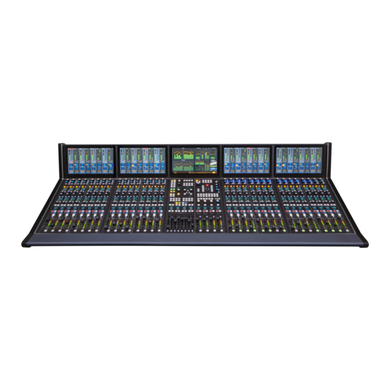
ARCUS TELEVISION CONSOLE
CHANNEL MONITORS (FADERS 1 - 16)
FOUR FADER MODULES *
(CHANNELS 1 - 16)
FADER CHANNEL STRIP CONTROLS
1. INPUT TRIM CONTROL - Adjusts the channel source's input gain.
1
2
2. ISOLATE - Isolates the channel from global preset changes when lit.
3
4
5
3. AUTOMIX - Identi es that channel is part of an AutoMix group when lit.
6
4. INPUT SELECT ENCODER - Use to select and take a new channel source.
7
5 - 6. PRESET SOURCES - Tap the A or B button to recall a preset source. Press/hold the
8
9
A or B button to change the source assigned to that A or B button.
7 - 22. WILD CONTROLS & DISPLAYS - The four encoders, eight buttons, and two displays
10
are used to view and adjust various channel parameters. The encoders (7, 14, 15, 22) are
11
used to both select and to then adjust a parameter along with the buttons (8, 9, 12, 13, 16,
17, 20, 21) and displays (10, 11, 18, 19). The channel control functions are saved/recalled as
a group using the Control Module's Wild Preset buttons, or universally changed by using
13
12
the Control Module's Function Expand buttons.
14
23 - TB (TALKBACK)
Used by the board operator to talk to that channel's bus-minus output.
15
24 - VCA
16
17
Adds the channel to a VCA group when lit.
25 - CHANNEL OLED DISPLAY
18
Shows the current source name and signal mode in the top half of the display. The source
19
info when Page is active for this channel is shown in the bottom half of the display.
26 - MUTE
21
20
When lit, the channel is muted. When unlit, the channel is feeding all assigned busses.
22
27 - SEL (Select)
23
24
When lit, indicates this channel is the selected channel which changes the channel
monitor to show channel-speci c settings for quick updates to the channel settings.
28 - SPILL
Sends the channel's audio to adjacent faders so those channel faders can be adjusted to
25
balance the audio. Most o en used with 5.1 sources.
26
27
29 - PAGE
Toggles the channel between showing Page A settings (unlit) and Page B settings (lit) for
28
the active Layer.
30 - AFL (AFTER FADER LISTEN)
29
Sends the channel audio, post fader, to the CR monitor.
30
31 - AUTOMIX INDICATORS
LEDs indicate whether the channel is in an Automix Group as a Master or Slave signal.
31
32 - INPUT LEVEL METER
32
Shows the source input levels of the source currently feeding that channel.
33 - GAIN REDUCTION METER
Shows the amount of Gain Reduction being applied to the channel audio.
34 - FADER
33
Controls the audio going to the assigned busses. For unity gain, align the fader knob line
34
with the thick line at -12.
35 - PFL (PRE-FADER LISTEN)
35
Sends the channel audio, pre-fader and pre-switch, to the PFL meter & cue output.
1 of 3
SURFACE COMPONENTS (ARCUS-32 SHOWN)
MULTI-TOUCH MONITORS*
MAIN MONITOR
CONTROL & MASTER MODULES
(SUBMIX, VCA GROUPS, MASTERS, MONITORS)
* The number of monitors and fader modules is set by the frame size
Quick Start Guide
CHANNEL MONITORS (FADERS 17 - 32)
FOUR FADER MODULES*
(CHANNELS 17 - 32)
FADER CHANNEL MONITOR DISPLAYS
NORMAL CHANNEL DISPLAYS
When no channel SEL buttons are lit, eight channel settings
are shown in the display. The channel number and On-Air
indicator is at the top. Input level and gain reduction meters
along with mode, delay, input gain, and master bus assign-
ments are in the middle. Mini EQ & Dynamics graphics show
their current settings with two Page presets below. Pressing
Aux Sends brings up a mini Aux Send control screen.
CHANNEL SEL ACTIVE DISPLAY
When a channel SEL button is lit, the channel monitor display
behind that channel changes to show the Input View (shown
above) so the board operator can quickly adjust various
channel parameters. The buttons along the bottom of the
display bring up additional displays to adjust Bus Assigns, EQ,
Dynamics, 5.1 signal panning, set AutoMix weightings, and a
adjust the Aux Sends. Tapping the Exit button returns the
monitor to its normal display, turning o the SEL button on the
active fader channel.
011598 rev A
Advertisement

Related Manuals for Wheatstone ARCUS


Summary of Contents for Wheatstone ARCUS
- Page 1 Quick Start Guide ARCUS TELEVISION CONSOLE SURFACE COMPONENTS (ARCUS-32 SHOWN) MULTI-TOUCH MONITORS* CHANNEL MONITORS (FADERS 1 - 16) MAIN MONITOR CHANNEL MONITORS (FADERS 17 - 32) FOUR FADER MODULES * CONTROL & MASTER MODULES FOUR FADER MODULES* (CHANNELS 1 - 16)
- Page 2 Quick Start Guide ARCUS TELEVISION CONSOLE MAIN MONITOR - HOME VIEW MAIN BUS METERING SUBMIX & MIX-MINUS METERING 5.1 SURROUND 1 / STEREO 1 / SWITCHED / STEREO 2 / 5.1 SURROUND 2 AUX MASTERS & TRACK METERING LOUDNESS MONITOR...
- Page 3 STATS & ALARMS VIEW BUS ASSIGN VIEW CLIP PLAYER VIEW REVERSE ROUTE VIEW EVENT VIEW MIX MINUS MASTERS VIEW ARCUS SURFACE, REAR PANEL CONNECTIONS To WheatNet-IP System (WNIP) SPS-400 Supply Gibraltar IP Mix Engine Links SPS-400 Supply Switch ports (standard) (opt.
Need help?
Do you have a question about the ARCUS and is the answer not in the manual?
Questions and answers