
Subscribe to Our Youtube Channel
Related Manuals for Wheatstone ARCUS


Summary of Contents for Wheatstone ARCUS
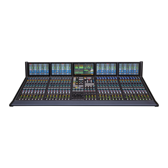
- Page 1 Networked AoIP Television Broadcast Console For WheatNet-IP Systems (AES67- & ST 2110-30-compatible) Designed & built by New Bern, North Carolina, U.S.A. Wheatstone manual p/n 011590 (Arcus-32 shown above)
-
Page 2: Publication Information
©2022 Wheatstone Corporation Wheatstone considers this document and its contents to be proprietary and confidential. Except for making a reasonable number of copies for your own internal use, you may not reproduce this publication, or any part thereof, in any form, by any method, for any purpose, or in any language other than English without the written consent of Wheatstone Corporation. -
Page 3: Table Of Contents
Arcus Surface Placement ..........11 Gibraltar Mix Engine ............12 Stagebox ................13 Final Surface Connections ..........13 Energizing Your Arcus Console ........14 3 – Arcus Apps and Console Configuration ......15 ❖ Navigator ................16 Arcus Surface Setup GUI ..........31 4 – Arcus Board Operations ..........45 ❖... -
Page 5: Introducing The Arcus Console
The other two OLED displays show various displays depending upon the func- Arcus Surface – Commonly referred to as the “console” since it has all tions assigned to the four sets of programmable controllers. the board operator controls on three types of plug-in modules: Fader, When a fader channel’s SEL button is lit, and the EQ or DYN... - Page 6 Just below the Hot Clip buttons are Talkback (TB) controls with eight dedicated talkback buttons and an OLED display to identify the as- ● EQ DSP Card—Has the DSP for the Arcus fader channels. This card signed talkback destinations. At the right side, four rotary encoders has no rear panel connections.
-
Page 7: Arcus Overview
The days of having cm) wide frame for the Arcus-16, or 74" (188 cm) wide for the Arcus-32. to block out channels, based on input type, is a thing of the past, as is console’s three... - Page 8 Chapter 3, starting on page 15, networked using one or more AoIP-compatible gigabit Ethernet switches. covers how to use the supplied apps to configure your Arcus console. Each WNIP device connects to an access port on a gigabit switch using a straight-thru CAT5e/CAT6 cable which can be up to 330 feet (100 meters) in length.
-
Page 9: Specifications
Gibraltar Mix Engine: <90 watts at 120 VAC / 60 Hz Arcus Surface & Supply: <80 watts at 120 VAC / 60 Hz Arcus-16 = 14.2” (36 cm) x 43" (109 cm) x 29.4" (75 cm) Stagebox: <60 watts at 120 VAC / 60 Hz Arcus-24 = 14.2”... -
Page 10: Warranty Statement
2. This Warranty is subject to the following restrictions and conditions: a) The owner must have filled out the enclosed Warranty Card and returned it to Wheatstone Corporation; or, at the time of servicing, the owner must provide proof of purchase from an authorized Wheatstone Corporation dis- tributor or dealer. -
Page 11: Arcus Hardware Installation
ARCUS SURFACE PLACEMENT The Arcus Surface cable connectors are on the vertical section of the lower rear chassis, near the right-rear corner (as viewed from the board operator’s position). Figure 2-1 shows the connections for the DC cables from the power supply and the crossover and straight-thru Ethernet cables connecting the Mix Engine and WNIP system Ethernet switch ports. -
Page 12: Gibraltar Mix Engine
Phillips screws. Power Supply The Arcus Surface is powered by a separate 2RU (3.5”) rackmount PSR Rack Unit (Figure 2-3). One SPS-432 slide-in supply is included with the Figure 2-3 Rear View, PSR rack with two SPS-432 DC Supplies Surface. -
Page 13: Stagebox
Surface Host card, to switch from the other ports on the Host cards are typically not used. RJ45 jacks to the fiber jacks, must be changed. If the Arcus was ordered Note: There are two USB ports: CLIP and USER located at the top with a QOT card, the switches are already set to use the fiber jacks rather of the right-most column of controls on the Master module. -
Page 14: Energizing Your Arcus Console
On a new console this will typically leave most, if not all, faders at time the normal rectangular ? button is again shown on the touchscreen. full off. The channel OLED displays show their current input sources (NoSource on every channel on a new console). The Arcus is now ready for use. -
Page 15: Arcus Apps And Console Configuration
Wheatstone file management site. Email Wheatstone Windows Start menu, the Navigator app is in the WheatNet IP folder, and the Arcus Surface Setup app is in the WheatNet IP Arcus folder. On a Win Tech Support for the download links: techsupport@wheatstone.com. -
Page 16: Navigator
To start Navigator, double-click its desktop icon or, from the Start Menu on Win10 PCs, select All Programs > Wheatstone > WheatNet IP Navigator. On a Win7 PC, select All Programs > Wheatstone > WheatNet IP > WheatNet IP Navigator. - Page 17 Crosspoint grid. The difference is that this grid is Lock Destination When On, is checked in the Arcus Surface Setup app not “live.” In the Salvo grid (Figure 3-3 on the next page) you connect the (Surface Options >...
- Page 18 AES67 to be added or removed. devices will be networked with Arcus. This tab is where the AES67 master clock source is set and sets whether AES67 sources and/or destinations are shown in the System Dock.
- Page 19 WNIP system. Signals are taken on a fader channel, as shown in Figure 3-5. selected as in the Visibilities tab in the Arcus Surface setup app (page 42 has signal selection details). Figure 3-5 Associated Connections Tab A Trigger Connection is assigned by clicking Add…...
- Page 20 The only signals which you can’t good insurance policy so you can recover a Blade’s configuration if meter in this tab are AES67 signals and the Arcus Mix Engine’s automatic recovery cannot work. destinations (console fader channels and external monitor inputs).
- Page 21 The Configuration Folder section sets the folder path for saving your system configuration files. The default path is: Documents > Wheatstone > Navigator > cfg. Clicking the … button opens a save dialog box to create a new folder and set the path. Clicking the Default button restores the Save To folder back to use the CFG folder in the default path.
- Page 22 Note that none of these affect the data saved to the E2 log file. The Network section shows the Network Interface (NIC) IP address To email log files to Wheatstone tech support, click the Zip… button to that’s connected to the WNIP system. If no devices appear in the System open a Zip Log Files window.
- Page 23 Click Refresh to rescan the system to update the list of connected Blade Tabs devices. Note that a similar view is available by clicking on System View, When a Blade—which includes the Mix Engine, the Stagebox, and PCs however in that view the Surfaces and other devices are shown under running the WNIP audio driver, is selected in the System Dock, the tabs separate tabs from the Blades.
- Page 24 The Source Signals and Destination Signals sections have four output, four stereo outputs, eight mono outputs, various buttons: Add…; Add Alias…; Edit…; and Delete. Clicking Add opens the Edit combinations of mono and stereo outputs. Signal window (shown in Figure 3-14) so you can add a new signal. The The logic resources are similarly updated when an audio signal with logic other three buttons require one to first select a signal then click Edit…...
- Page 25 Once you add Alias names and complete editing the source and On a Stagebox, each analog input and output is factory-set as a mono destination names use the Arcus Surface Setup app to run a new System signal while the AES inputs and outputs are set as stereo signals. These Scan (see pages 31 &...
- Page 26 Press Enter to set the new number. to connect legacy devices that use hardware GPIO Figure 3-16 Stagebox LIO Connector • On the Arcus channel strip, rotating the Gain control also adjusts (General Purpose Input/ vs.
- Page 27 Off Tally logic back to the TS to light up the On and Off buttons. These the Arcus Mix Engine have 128 “Soft” or SLIO signals which can be used to are assigned to Soft LIOs since the TS is a networked device. Figure 3-17...
- Page 28 Functional LIOs show Blade status; and Surface 1 Spares appear when that Blade is hosting a Surface. On an Arcus Mix Engine, the Surface 1 Spares section is where the sixteen Spare buttons on the Master Module can be assigned to fire a Salvo, make a momentary connection, and/or Take a Blade Processor Preset, as shown outlined in Figure 3-18.
- Page 29 3-22 the Visibilities tab. The Stagebox and Figure 3-20 Blade Info Tab Arcus Mix Engine The entries in the Info and Network Info sections with black do not have this backgrounds (Blade Name, IP Address, Subnet, and Gateway) can be tab since they do edited.
- Page 30 Figure 3-25 shows the Audio Player tab, which is like the Clip Player built into the Arcus Surface. One can play test signals or other audio to test routing. In TV applications, it’s often used for a confidence feed source to let remote users know they’re connected to the station.
-
Page 31: Arcus Surface Setup Gui
Surface, or the name of a configuration Start menu. In Win7 PCs it’s in the Wheatstone > file being edited). Two Surface action Wheatstone IP Arcus folder. In Win10 PCs it’s in the buttons (Reset and Apply) are at the right Wheatstone category. - Page 32 Click on Blades to view the Mix Engine (which is a type of Exit—closes the app. Same as clicking the X app close button in the ❖ Blade) and all other Blades and Stageboxes networked with Arcus. upper right corner of the window. Note: As Source...
- Page 33 Surface Versions. Help About…—opens a window which lists the version number of the ❖ Arcus Surface Setup app along with where the various files used by the app are saved. Figure 3-28 Getting Started tab Connect to a Surface Getting Started Tab The Surface’s current configuration settings are read, and compared,...
- Page 34 Arcus while it reboots. used to edit the IP addresses assigned to the Mix Engine cards when a different class-C subnet is used or when multiple Arcus consoles will be Factory Reset Surface Info… Resets the selected Mix Engine and the networked together.
- Page 35 Blade ID and IP address to the Mix Engine Blade Info entry boxes. This level until a Surface control is touched, which immediately returns the action sets that Mix Engine as the host device for the Arcus Surface that’s OLED displays to their Normal Level setting.
- Page 36 Track signal (stereo or 5.1) and a mono Bus Minus signal associated Although this may be desirable for console configuration, it’s not with it. The Arcus Master 1 and 2 outputs are set for Surround 5.1 audio recommended for normal operations—especially when the OLED while the Master 3 and 4 outputs are set for stereo audio.
- Page 37 Switch LED 1, which cannot be edited. assign the buttons’ logic control functions. In Navigator select the Arcus Mix Engine: Bridge IP then select the LIO Info tab. Expand the Surface 1 Spares section (Figure 3-33). This tab is where a Spare button can be set to Fire a Salvo;...
- Page 38 Surface Options Tab Allow Source Select When Locked—sets whether channel source selection is active while a channel is on and Lock Destination When On is There are six page tabs under this tab: General, VDips, Visibilities, checked. When this option is also checked, an alternate source can be Operator Access, Monitor Config, and Master Faders, which are used selected on a channel that’s on.
- Page 39 NOT listed in the Signals list. the Signals list is the Default entry row. Select this row to assign the logic attributes that every source connected to the Arcus should use. You can set any combination of the settings in the Options, Monitor Mutes, Monitor Tallies, and Bus Minus Base Mix sections.
- Page 40 (tally logic) is sent. have control over the listed Surface Remote Ready—this feature has no application on the Arcus since the and/or channel channels don’t have a separate Off button and LED. Remote Ready is used function.
- Page 41 The Ctrl Rm mute can be used for Master Control to mute the monitors When both are unchecked, as shown above, the audio feeding the base when talking to the studio. If the Arcus board operator has a microphone mix is controlled just like the audio feeding a Master output: both the...
- Page 42 (the default setting for a new Arcus console). Click on a right-facing arrow to expand that device tree (the arrow then points down). Sub-categories (Blade, User, Alias, Surface, etc.) are expanded in like manner until you reach the...
- Page 43 Operator Access Page Tab Surface with the new setting. The unchecked bus assignment This page tab (Figure 3-40) has four sections: Configure Air Switch, buttons are now fixed, and board Events, Bus Assignments, and Miscellaneous. During console configuration operator cannot change the bus all settings are typically left checked, but these settings may be selectively assignment for the unchecked unchecked—prior to releasing the console for daily operations, to prevent...
- Page 44 Monitor Config Page Tab Master Faders Page Tab The Monitor Config page tab (Figure 3-41 on the next page) sets This page tab (Figure 3-42) allows the names shown in the four Master whether any monitor destination should have its level locked. When Level outputs OLED displays to be edited.
-
Page 45: Arcus Board Operations
● Fader Section—At the bottom of the channel strip, palm rest. Whenever you enter the control room to work on the Arcus, we has the main info display and the channel fader along recommend momentarily touching the palm rest prior to touching any with various channel-specific push button controls. - Page 46 strip’s settings may change when the Layers, Side switch to display, and control, the various EQ, Shift, or Pages buttons are used on the Control DYN (Dynamics), Aux (Aux Sends), or Track module. controls which only affect the selected channel strip.
- Page 47 Table 4-1 DSP Faders vs. Physical Faders applied to the channel’s audio. On an Arcus-16, one must go thru six Layers to show all 96 DSP input 11 – FADER—Controls the audio level going to channels, in groups of sixteen, since the Arcus-16 only has sixteen the assigned busses when the On button is lit.
- Page 48 The Page buttons on the channel strips allow one to toggle between two their parameter settings, will not change as one switches Layers. DSP input channels. On a new Arcus-24 console, pressing the Page button on channel strip 24 switches that channel strip to show DSP input channel Channel Info Display 48.
- Page 49 To use this function, the engineering staff The PFL and AFL buttons blink while active. must connect a talkback mic for the Arcus board operator which is then cross-connected to the console’s Talkback destination. The fader channel’s Note: If one or more PFL and AFL buttons are blinking on the bus minus signal must also be cross-connected to feed the talent’s in-ear...
-
Page 50: Master Module
Clip player settings are Fader Level also saved as part of an The Arcus uses motorized 100 mm faders so that the input Event allowing a selected channels faders are accurately positioned when switching audio track to be loaded between Layers. -
Page 51: Control Module
Section 5 has the master faders for the four main outputs on an Arcus active Layer. Press Undo console: Outputs 1 and 2 are 5.1 Surround while Outputs 3 and 4 are to undo the last action. -
Page 52: Touchscreen Monitors
Multi-Touch Monitors meter. Outputs 3 and 4 are stereo outputs (ST1 and ST2) with Each Arcus Surface has multiple 16x9 1080p monitors with multi-touch left/right metering plus a Gain Reduction meter. A Switched stereo control using the same multiple finger gestures as used with smart phones meter lies between the two Stereo Meters. - Page 53 Selecting a View To switch from the Home view, tap on, or use a mouse to click on, one of the other thirteen View buttons which are along the bottom of the Main Monitor. Figure 4-10 Main Monitor View Buttons Note: Not all views are always available.
- Page 54 USB memory stick, then rename it as Events. When that memory master level for that bus or signal (the motorized fader for the active stick is plugged into the Arcus Master module, and the Events signal will follow any slider movements and vice versa).
- Page 55 The six buttons in this section are used to edit an existing Event or to master Auxiliary Send busses, which are Arcus sources: AUX 01–AUX 16. create a new Event. To create a new Event, setup the Surface for that...
- Page 56 These functions are easily done using the Navigator app, but if set to feed PFL (PFL is lit), or that talk to that mix-minus is active that app is not available near the Arcus console this view’s controls can be (Talkback is lit).
- Page 57 Reverse Route View sixteen Auxiliary Send busses. Tap on a rotary control to select that Aux This view (Figure 4-20) allows a board operator to quickly assign Send bus. In Figure 4-21 Aux 1 is selected. The box around the four multiple sources to specific busses.
- Page 58 Figure 4-23 Dynamics DYN View Figure 4-22 5.1 Pan View The audio signal can be balanced by dragging the crosshairs or by Gate Functions dragging one of the arrows to manually adjust one speaker level. Tapping The five Gate controls at the top of this view set how the automatic one of the ten buttons at the top, its box is outlined in gold, puts control signal attenuator functions.
- Page 59 triggering the ducking or gating, while using a fast OPEN setting ensures As the audio becomes louder than the THRESH setting, the compressor the audio isn’t “upcut” as the mic is used after it is ducked or gated. begins to clamp down on the audio output level following the RATIO setting which ranges from 1.0:1 (no compression) to 20:1 (it effectively When gain reduction needs to be subtle, so as not to draw attention to functions as a signal limiter).
- Page 60 Master channel SEL button is active. The view allows the board operator to turn equalization for the selected channel or bus on or off and adjust it as required. The Arcus EQ is a four-band parametric equalizer with adjustable high and low pass filters. Two of the parametric EQs can be set as LO SHELF and HI SHELF equalizers.
- Page 61 affecting the voice sound—until the control is adjusted below about 5 kHz. shown below the meter along with indicators listing which Master busses Audio above the selected frequency is rolled off at 24 dB/octave while that signal is assigned to. If any EQ or Dynamics are assigned, the two audio below that frequency is not affected.
- Page 62 Section 3 – Bus Minus controls The track audio can be monitored post track fader control by tapping the This section has the controls for the input channel’s Bus Minus or Direct AFL button. The board operator can also talk into the Track output by Out signal.
- Page 63 AUTO PLAY button. The cued track is then played when channel ON is This View brings up the controls for the Arcus audio clip player, used to pressed. If EFS (Electronic Fader Start) is active, moving the channel fader play back audio tracks from a USB flash drive plugged into either USB port up from full off turns the channel on and starts track playback.
- Page 64 ❖ lishing and -Maintaining Audio Loudness for Digital Television. loudness of the program material being mixed on the Arcus console for recording or broadcast. Logging functions allow the engineering staff to EBU-TECH 3341 Loudness Metering: EBU Mode metering to sup- ❖...
- Page 65 Arcus Destination Loudness. This allows for monitoring any analog, Operators must understand that the large digit value is integrated over AES, MADI, or SDI source, as well as any Arcus mix bus, de-modulated time and thus will not instantaneously react to any fader moves. Operators program source, pre-recorded programming, or other source.
-
Page 66: Arcus Service Information
PARTS AND REPAIR SERVICES 011566 HC-IP64 Host Card A list of the field-replaceable parts on the Arcus console is in Table 5-1. 011560 OL1 – single OLED Display (plug-in assembly) Control module assemblies, and the other circuit boards used on the Arcus 011561 OL2 –... - Page 67 ● 2 & 4 on, 1 & 8 off = Module 6 (right-most module in Arcus-16) operating at 100 MB speed. The Arcus Host card and the Mix Engine CPU ● 1, 2 & 4 on, 8 off = Module 7 both use 100 MB NICs since they don’t carry streaming audio signals.
-
Page 68: Software Updates
Arcus Surface. Interface. Blades can be individually updated, or all Blades can be updated If there’s a new release of the Arcus Surface Setup app, it may also simultaneously. Note that Navigator must be licensed to use the Blade contain new Surface software installed with the Arcus Surface Setup app software update feature. -
Page 69: Appendix Acreating A Wheatnet-Ip Network
ETHERNET SWITCHES FOR AOIP help you identify how many switch ports you’ll need by listing every device For a stand-alone Arcus console used in a remote truck or sound stage that will be networked with your WNIP system. This will include the Arcus with one or two Stageboxes for I/O, one could get by using a single 8-port Surface host PCs, the Mix Engine’s CPU and GBT cards, the Stagebox and... - Page 70 9300-series models are commonly used for TOC switches. being networked together, and how much equipment in the TOC is also For a remote truck or a venue with one Arcus console along with a being networked, the Core Network Switch might physically consist of Stagebox for I/O, one 8 or 12-port switch should be sufficient.
- Page 71 Wiring Practices use Wheatstone Navigator’s Crosspoint grid, or use a system salvo, to Since most of the wiring used for new builds in TV and radio broadcast switch the return connections to the codecs.
Need help?
Do you have a question about the ARCUS and is the answer not in the manual?
Questions and answers