
Related Manuals for Wheatstone G-5


Summary of Contents for Wheatstone G-5
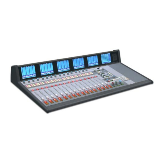
- Page 1 G-5 Digital Control Surface TECHNICAL MANUAL 600 Industrial Drive, New Bern, North Carolina, USA 28562...
- Page 2 G-5 Digital Control Surface Technical Manual - 1st Edition G-5 Digital Control Surface Technical Manual - 1st Edition G-5 Digital Control Surface Technical Manual - 1st Edition G-5 Digital Control Surface Technical Manual - 1st Edition G-5 Digital Control Surface Technical Manual - 1st Edition ©2003 Wheatstone Corporation...
- Page 3 Any modifications not expressly approved in writing by Any modifications not expressly approved in writing by Wheatstone could void the user's authority to operate this equipment. Wheatstone could void the user's authority to operate this equipment. Wheatstone could void the user's authority to operate this equipment.
- Page 4 Caution! Do not use ammonia based cleaning solutions as they can cause the surface to yellow, and became brittle and eventually cause structural damage to the acrylic surface. Wheatstone will not be liable for damage resulting from improper cleaning and maintenance. R R R R R...
-
Page 5: Table Of Contents
Studio Section ...................... 3-3 Headphone Section ..................... 3-4 Talkback ......................3-4 CUE Section ......................3-4 Switched Meters Section ..................3-5 Mode Select Section ....................3-5 MXM Master Outputs ....................3-6 MXM Assign ......................3-6 page Contents – 1 G-5 / Sep 2003... - Page 6 “ETH B” RJ-45 - Optional Redundant Computer Ethernet Connector ..... 5-4 “CAT5” RJ-45 - Mixer Link Connector ..............5-4 Typical Ethernet Cable ..............5-5 Typical Crossover Cable ..............5-5 page Contents – 2 G-5 / Sep 2003 G-5 / Jan 2006...
- Page 7 Schematic ........................ 6-33 Load Sheet ....................... 6-34 PWI-5.1 Power Interface Card Schematic ........................ 6-35 Load Sheet ....................... 6-36 PSU-1 Power Supply Schematic ........................ 6-37 Load Sheet ....................... 6-38 page Contents – 3 G-5 / Sep 2003 G-5 / Jan 2006...
- Page 8 Introduction ......................A-6 Modifying The Options Text File................A-6 A Sample Example From The File .................A-7 A Second Example ....................A-8 An Example File - Complete...................A-9 Appendix 3 Replacement Parts List ............A-12 page Contents – 4 G-5 / Sep 2003 G-5 / Jan 2007...
- Page 9 Power Supply ................1-4 Failsafe Dual Redundant Supply ................1-5 Energizing ....................... 1-5 I/O Connections ................1-6 The Insulation Displacement Connector System ..........1- 6 Wiring Procedure - Double Connection to One Pin ..........1-8 page 1 – 1 G-5 / Sep 2003...
-
Page 10: Introduction
Wheatstone’s proven BRIDGE technology. Designed to integrate flawlessly with the Wheatstone BRIDGE digital audio network router, the G-5 control surface allows you to easily create large or small platform-based systems that are exceptionally user-friendly and flexible. Wheatstone BRIDGE network cages house all I/O ports and engine cards,... -
Page 11: Control Surface Placement
Cutout dimensions (in inches) are shown in the drawings below for the three available frame sizes. Do not connect the G-5 control surface to its power supply (and do not connect the power supply to the AC power line) until instructed to do so. -
Page 12: Power Supply
Rear view of the PSU-1 rackmount power supply If failsafe redundant sup- The G-5 control surface is powered by a Wheatstone Model PSU-1 plies have been ordered, rackmount power supply. This unit occupies two 19” wide rack spaces you will be installing two PSU-1 units. -
Page 13: Failsafe Dual Redundant Supply
BOTH rackmount supplies powered up and connected to their associ- ated equipment. Energizing Assuming the G-5 control surface mainframe is properly placed, and its PSU-1 power supply (or supplies) correctly rackmounted and connected to the control surface, you may now energize the rackmount power supply by plugging it into the AC mains. -
Page 14: I/O Connections
G E N E R A L I N F O R M A T I O N I/O Connections All user wiring to and from the G-5 control surface is made via connectors located on the control surface’s rear panel. Two 5-pin male connectors at the left end of the control surface’s rear are for power supply... - Page 15 Note that mating hoods for each connector are also supplied with the system. These have locking screws that hold the connectors securely to their mates. page 1 – 7 G-5 / Sep 2003 G-5 / Jan 2006...
-
Page 16: Wiring Procedure - Double Connection To One Pin
Wiring Procedure - Double Connection to One Pin ref: DB-25 male multi-pin connector Most audio equipment machine interfaces (as well as Wheatstone consoles) use subminiature D-type connectors. Sometimes the interfaces require making two connec- tions to a single DB pin. If the wiring has been set up using punchblocks, this is not a problem;... - Page 17 CUE Switch ......................2-3 Fader ........................2-4 ON/OFF Switches ....................2-4 LCD Display ......................2-4 Input Level ......................2-4 Selected Source ....................2-5 Channel Status ....................2-5 Null Indicators ....................2-5 Channel Number ....................2-5 page 2 – 1 G-5 / Sep 2003...
-
Page 18: Controls And Functions
I N P U T P A N E L Input Panel (IS-G5) Controls and Functions Each input panel of the G-5 digital audio control surface has four identical strips representing four input channels. Input Sources Each input panel controls four stereo sources. By... -
Page 19: Pan/Balance Knob
SET button is pressed, or until a timeout of about 10 seconds has occurred. CUE Switch The CUE switch lets the operator monitor the channel’s pre-fader signal. page 2 – 3 G-5 / Sep 2003 G-5 / Feb 2004... -
Page 20: Fader
The level is indicated in DB on a calibrated scale showing beside the bargraph. If the channel is stereo, the bargraph shows the sum of left and right signals. The bargraph is colored, with page 2 – 4 G-5 / Sep 2003 G-5 / Feb 2004... -
Page 21: Selected Source
“DOT” over a solid “COLUMN” where the “DOT” indicates the peak value of the signal, and the “COLUMN” indicates the average value. On the G-5 control surface the average value column has been set to VU timing characteristics. In addition, a bright yellow rectangle will light at the top of the column if digital “OVER”... - Page 22 Establishing the Default Setting ................ 3-9 Storing an Event ....................3-9 Naming an Event ....................3-9 Modifying the Currently Selected Event ............3-10 Control Modes ....................3-10 Information Display ....................3-11 page 3 – 1 G-5 / Sep 2003 G-5 / Aug 2004...
-
Page 23: Chapter 3 - Control Panel (Efs-G5)
C O N T R O L P A N E L Control Panel (EFS-G5) Controls and Functions The G-5 digital audio control surface is equipped with one CONTROL panel. This panel contains MONITORS, CUE, SOLO, TALKBACK, MODE, MXM MASTER OUTPUTS, EVENT, TIMER, and SWITCHED METERS controller sections. -
Page 24: Control Room Section
ST DISPLAY - the eight character display shows the source that is selected for monitoring in the studio. ST LEVEL CONTROL - determines the overall loudness of the signal being monitored as it appears in the studio speakers. page 3 – 3 G-5 / Sep 2003 G-5 / Feb 2004... -
Page 25: Headphone Section
Similar to the control room speakers, the cue speaker also has the potential for feedback and should be muted (using the configuration software—VDIP menu) whenever the control room speakers are. page 3 – 4 G-5 / Jul 2005 G-5 / Sep 2003... -
Page 26: Switched Meters Section
SET button of the desired channel or mix; the SET button will illuminate, and the current mode setting for that channel will be displayed on the MODE switches. MODE can be reconfigured by pressing any allowable button. page 3 – 5 G-5 / Sep 2003 G-5 / Jan 2005... -
Page 27: Mxm Master Outputs
Time of Day Clock The MASTER LCD SCREEN includes the display of a time of day clock. To set the time on this clock you run a Wheatstone utility program, WSTimeSet.exe, on a network computer. The program allows you to set the clocks on multiple control surfaces by specifying the IP addresses of the page 3 –... -
Page 28: Xy Controller Section
TAKE button to execute the command and the new destination will become the current destination, shown in available displays elsewhere on the control surface. Disallowed destinations (established in the con- figuration software) will not be shown. page 3 – 7 G-5 / Sep 2003 G-5 / Aug 2004... -
Page 29: Removing Output Mix Destinations
(the one just taken) becoming page 3 – 8 G-5 / Sep 2003 G-5 / Dec 2004 G-5 / Jan 2005... -
Page 30: Event Default Button
ALPHA SCROLL knob. Also, if you stop making name changes but fail to press the SAVE button, the name edit process will automatically cancel after a delay of several seconds. page 3 – 9 G-5 / Sep 2003 G-5 / Feb 2004... -
Page 31: Control Modes
Control Modes The G-5 control surface is operated in one of three modes. In Administrator mode access is allowed to all surface functions. In User mode a limited set of user functions is allowed. The set of functions allowed in User mode is set independently for each console using the Bridge XPoint software (see the Bridge Router manual for details). -
Page 32: Information Display
PHONE, and STUDIO control knobs at the same time. Push down the same three knobs again to revert to the normal screen. page 3 – 11 G-5 / Sep 2003 G-5 / Feb 2004 G-5 / Aug 2004 G-5 / Aug 2004... -
Page 33: Chapter 4 - Dcm Control Panel (Dcm-G5)
D Y N A M I C S P R O C E S S I N G C O N T R O L P A N E L DCM Control Panel (DCM-G5) Chapter Contents Controls and Functions ............. 4-2 Programmable Buttons ................... 4-2 Display Buttons ....................... 4-3 page 4 – 1 G-5 / Sep 2003... -
Page 34: Controls And Functions
LEDs on the Spare buttons may also be lit by a remote device connected to a Logic card input port. See the Bridge Router manual for details. page 4 – 2 G-5 / Sep 2003 G-5 / Aug 2004... -
Page 35: Display Buttons
D Y N A M I C S P R O C E S S I N G C O N T R O L P A N E L Display Buttons These switches control the display modes for the LCD monitor. Not Used page 4 – 3 G-5 / Sep 2003... - Page 36 Typical Ethernet Cable .............. 5-5 Typical Crossover Cable ............5-5 Optical Fiber Interface ............... 5-6 Connector Type ...................... 5-6 Optical Fiber Cable....................5-6 HC-9 Pinouts Drawing ............... 5-7 Cue Speaker/Headphone Pinouts Drawing ......5-8 page 5 – 1 G-5 / Jan 2006...
-
Page 37: Overview
Keyboard, floppy controller and video ports are for factory use only. The purpose of the host controller is to provide control of the G-5 control surface. The HC-9 communicates to the XPoint Configuration PC via TCP/IP over Ethernet through a standard ethernet hub or switch. It also communicates to the Bridge Router system via a special mixer link connection. -
Page 38: Mixer Link Wiring
SW8 Position 4 - CAT5 vs. Fiber The mixer link can be connected via CAT5 cable or fiber optic cable. Set position 4 of SW8 on if you are using CAT5 or off if you are using fiber. page 5 – 3 G-5 / Jan 2006... -
Page 39: Hook-Ups
Pin 1 – TXD + Pin 2 – TXD - Pin 3 – RXD + Pin 4 – N/C Pin 5 – N/C Pin 6 – RXD - Pin 7 – N/C Pin 8 – N/C page 5 – 4 G-5 / Jan 2006... - Page 40 RXD - Orange Green RXD + TXD + White/Green White/Orange RJ-45 RJ-45 Plug Blue Blue Plug White/Blue White/Blue RXD - TXD - Green Orange White/Brown White/Brown Brown Brown SED FOR MIXER LINK CONNECTOR page 5 – 5 G-5 / Jan 2006...
-
Page 41: Optical Fiber Interface
H A R D W A R E Optical Fiber Interface The G-5 control surface supports an optional fiber connection to the Bridge Router. Connector Type An SC Duplex style connector is provided for inter- facing optical fiber. The SC (subscription channel) con- nector is a low insertion loss, locking mechanism with excellent strain relief characteristics. - Page 42 RXD - RXD - LN LED LN LED LK LED LK LED Mixer Link Connections CAT5 Optional Optical Connector FIBER (RJ-45) (SC Connector) TXD + TXD - RXD + (crossover) RXD - page 5 – 7 G-5 / Jan 2006...
- Page 43 H A R D W A R E Cue Speaker /Headphone Pinouts "CUE SPKR/HDPN" FEMALE DB-9 5 4 3 2 1 (located at the left end of the control surface's rear) page 5 – 8 G-5 / Jan 2006...
-
Page 44: Schematic
Schematic ........................ 6-33 Load Sheet ....................... 6-34 PWI-5.1 Power Interface Card Schematic ........................ 6-35 Load Sheet ....................... 6-36 PSU-1 Power Supply Schematic ........................ 6-37 Load Sheet ....................... 6-38 page 6 – 1 G-5 / Sep 2003 G-5 / Nov 2005... - Page 45 6 - 2 G-5/Sep 2003...
- Page 46 6 - 3 G-5/Sep 2003...
- Page 47 6 - 4 G-5/Sep 2003...
- Page 48 IP-5 4 Inputs Panel Switch Card Load Sheet page 6 – 5 G-5 / Sep 2003...
- Page 49 6 - 6 G-5/Sep 2003...
- Page 50 S C H E M A T I C D R A W I N G S ONS-5 4 Inputs Panel On/Off Switch Load Sheet page 6 – 2 page 6 – 7 G-5 / Sep 2003...
- Page 51 6 - 8 G-5/Sep 2003...
- Page 52 6 - 9 G-5/Sep 2003...
- Page 53 6 - 10 G-5/Sep 2003...
- Page 54 6 - 11 G-5/Sep 2003...
- Page 55 6 - 12 G-5/Sep 2003...
- Page 56 MN-5 4 Control Panel Switch Card Load Sheet page 6 – 13 G-5 / Sep 2003...
- Page 57 6 - 14 G-5 / Sep 2003...
- Page 58 6 - 15 G-5 / Sep 2003...
- Page 59 DCM-5 DCM Panel Switch Card Load Sheet page 6 – 16 G-5 / Sep 2003...
- Page 60 6 - 17 G-5 / Sep 2003...
- Page 61 S C H E M A T I C D R A W I N G S IQ-9 IQ Card Load Sheet page 6 – 3 page 6 – 18 G-5 / Sep 2003...
- Page 62 10.0K 10.0K 0.1uF 0.01uF 0.1uF 0.1uF 0.1uF 0.1uF ____ R172 1.00K BP_BD_ID[7]_U R189 10.0K BP_BD_ID[7]_L 1.00K BP_BD_ID[7]_M ISSUED SIZE FSCM NO. DWG. NO. 84S01xx XC18V04 W# 700740 HC-9B PCB 1 OF 7 SCALE SHEET page 6 - 19 G-5/May 2005...
- Page 63 - SA UR US - Sergey Averin - 0.1uF 0.1uF 0.01uF 0.01uF 0.01uF APPROVALS DATE DRAWN 12-9-03 600 Industrial Drive New Bern, NC 28562 CHECKED ISSUED SIZE FSCM NO. DWG. NO. 84S01xx W# 700740 HC-9B PCB 2 OF 7 SCALE SHEET page 6 - 20 G-5/May 2005...
- Page 64 C167 C169 CHECKED AT_P4 0.01uF 0.01uF 0.01uF 0.01uF 0.01uF 0.01uF 0.01uF 0.01uF 0.01uF 0.01uF 0.01uF 0.01uF ISSUED SIZE FSCM NO. DWG. NO. 84S01xx 8952_RX+ AT_P3 W# 700740 HC-9B PCB 3 OF 7 SCALE SHEET page 6 - 21 G-5/May 2005...
- Page 65 LT1117 0.1uF 2.5V 0.1uF 100uF 150uF 0.01uF 0.01uF 0.01uF 0.01uF 0.01uF 0.01uF 0.01uF 0.01uF 0.01uF 0.01uF 0.01uF 0.01uF ISSUED SIZE FSCM NO. DWG. NO. 84S01xx W# 700740 HC-9B PCB 4 OF 7 SCALE SHEET page 6 - 22 G-5/May 2005...
- Page 66 LT1117 0.1uF 2.5V 0.1uF 100uF 150uF 0.01uF 0.01uF 0.01uF 0.01uF 0.01uF 0.01uF 0.01uF 0.01uF 0.01uF 0.01uF 0.01uF 0.01uF ISSUED SIZE FSCM NO. DWG. NO. 84S01xx W# 700740 HC-9B PCB 5 OF 7 SCALE SHEET page 6 - 23 G-5/May 2005...
- Page 67 0.1uF 100uF 150uF 0.01uF 0.01uF 0.01uF 0.01uF 0.01uF 0.01uF 0.01uF 0.01uF 0.01uF 0.01uF 0.01uF 0.01uF 0.01uF 0.01uF 0.01uF ISSUED SIZE FSCM NO. DWG. NO. 84S01xx W# 700740 HC-9B PCB 6 OF 7 SCALE SHEET page 6 - 24 G-5/May 2005...
- Page 68 - SA UR US - Sergey Averin - +5_LCD_SW_2 APPROVALS DATE +5_LCD_SW_3 DRAWN 12-9-03 600 Industrial Drive New Bern, NC 28562 1.00K 1.00K 1.00K CHECKED ISSUED SIZE FSCM NO. DWG. NO. 84S01xx W# 700740 HC-9B PCB 7 OF 7 SCALE SHEET page 6 - 25 G-5/May 2005...
- Page 69 HC-9 Host Controller Card Load Sheet page 6 – 26 G-5 / May 2005...
- Page 70 6 - 27 G-5 / Sep 2003...
- Page 71 BP-9 Back Plane Card Load Sheet page 6 – 28 G-5 / Sep 2003...
- Page 72 6 - 29 G-5/Sep 2003...
- Page 73 S C H E M A T I C D R A W I N G S BPR-9 Back Plane Repeater Card Load Sheet page 6 – 5 page 6 – 30 G-5 / Sep 2003...
- Page 74 6 -31 G-5 / Sep 2003...
- Page 75 S C H E M A T I C D R A W I N G S 32VC5-5 +5V DC to DC Converter Card Load Sheet page 6 – 4 page 6 – 32 G-5 / Sep 2003...
- Page 76 6 - 33 G-5 / Sep 2003...
- Page 77 S C H E M A T I C D R A W I N G S VU-9 VU Receiver Card Load Sheet page 6 – 6 page 6 – 34 G-5 / Sep 2003...
- Page 78 6 - 35 G-5/Sep 2003...
- Page 79 S C H E M A T I C D R A W I N G S PWI-5.1 Power Interface Card Load Sheet page 6 – 7 page 6 – 36 G-5 / Sep 2003...
- Page 80 - SA UR US - Sergey Averin - APPROVALS DATE 600 Industrial Drive DRAWN 8-16-05 New Bern, NC 28562 CHECKED SIZE FSCM NO. DWG. NO. 00S00xx ISSUED W# 700828 PSU-1A PCB 1 OF 1 SCALE SHEET page 6 - 37 G-5/Nov 2005...
- Page 81 S C H E M A T I C D R A W I N G S PSU-1 Power Supply Load Sheet page 6 – 8 page 6 – 38 G-5 / Nov 2005 G-5 / Sep 2003...
- Page 82 Modifying The Options Text File................A-6 A Sample Example From The File ................A-7 A Second Example ....................A-8 An Example File - Complete..................A-9 Appendix 3 Replacement Parts List .............. A-12 page A – 1 G-5 / Jan 2007 G-5 / Jan 2007...
- Page 83 A P P E N D I C E S Appendix 1 Contents Control Surface Clock ..............A-3 Setting the Time ......................A-3 Update Options ......................A-3 Synchronize ......................A-3 Battery Backup ......................A-4 page A – 2 G-5 / Jan 2007 G-5 / Jan 2007...
-
Page 84: Control Surface Clock
MASTER LCD screen. Setting the Time Setting the time of the control surface’s clock is made via the Wheatstone Surface Time Manager software: 1. Select Edit / Add Surface... from the Main Menu, which will display the following form. -
Page 85: Battery Backup
(it will do this for 3 to 4 weeks). To activate battery backup of the control surface’s clock simply pull out the yellow strip from the HC-9 board, as shown on the picture below. page A – 4 G-5 / Jan 2007... - Page 86 Introduction ....................... A-6 Modifying The Options Text File ................A-6 A Sample Example From The File ................A-7 A Second Example ....................A-8 An Example File - Complete ..................A-9 page A – 5 G-5 / Jan 2007 G-5 / Jan 2007...
-
Page 87: Options Text File
Options Text File Introduction There are a number of operational features on the G-5 surface that are controlled by the contents of the Options Text File (G5_OPTS.TXT) that resides on the surface's flash drive. In order to configure these features it is necessary to modify this file. - Page 88 The edited line must follow the established syntax precisely or the surface may not behave as expected. page A – 7 G-5 / Jan 2007 G-5 / Jan 2007...
-
Page 89: A Second Example
In any event you can select the same or a different mode from the available modes for each programmable button on the surface. page A – 8 G-5 / Jan 2007 G-5 / Jan 2007... -
Page 90: An Example File - Complete
4 = Automation, Button & LED are controlled by automation interface 5 = Preset Select, Button selects pre-configured preset, LED controlled by Surface SPARE1:2 SPARE2:2 SPARE3:2 SPARE4:2 SPARE5:2 SPARE6:2 SPARE7:2 SPARE8:2 SPARE9:2 SPARE1Ø:2 SPARE11:2 SPARE12:2 page A – 9 G-5 / Jan 2007 G-5 / Jan 2007... - Page 91 // ? 1 = use hardware logger, Ø (default) no hardware logger. HDW_LOGGER:Ø // Syntax: CLOCK_24HR:? // ? Ø (default) = 12 hour clock, 1 = 24 hour clock. CLOCK_24HR:Ø page A – 10 G-5 / Jan 2007 G-5 / Jan 2007...
-
Page 92: Appendix
Replacement Parts List ..............A-12 For the most part there are no user-replaceable parts in the G-5 control surface. Exceptions are those controls and components that in the course of normal use may need maintenance (i.e., faders, pots, ON/ OFF switches, etc.). A complete list of available components is shown on the next page. - Page 93 A P P E N D I C E S REPLACEMENT PARTS — G-5 CONTROL SURFACE COMPONENT DESCRIPTION WS P/N IS-G5 PANEL COMPLETE INPUT PANEL "005600" EFS-G5 PANEL COMPLETE CONTROL PANEL "005601" DCM-G5 PANEL COMPLETE DYNAMICS CONTROL PANEL "005607" BK-G5N BLANK PANEL FACEPLATE ASSEMBLY NARROW "005618"...
- Page 94 A P P E N D I C E S REPLACEMENT PARTS — G-5 CONTROL SURFACE COMPONENT DESCRIPTION WS P/N REPLACEMENT SWITCH ON/OFF SWITCH "510109" SWITCH RED BUTTON ON BUTTON "530097" SWITCH ORANGE BUTTON OFF BUTTON "530098" RED LED LAMP REPLACEMENT ON LED LAMP "600027"...
- Page 95 A P P E N D I C E S REPLACEMENT PARTS — G-5 CONTROL SURFACE COMPONENT DESCRIPTION WS P/N LUMA BUTTON STYRENE WITH UV INHIBITOR BUTTON PRINTED "1" "530297" LUMA BUTTON STYRENE WITH UV INHIBITOR BUTTON PRINTED "2" "530298"...
Need help?
Do you have a question about the G-5 and is the answer not in the manual?
Questions and answers