
Related Manuals for Wheatstone TV 1000


Summary of Contents for Wheatstone TV 1000
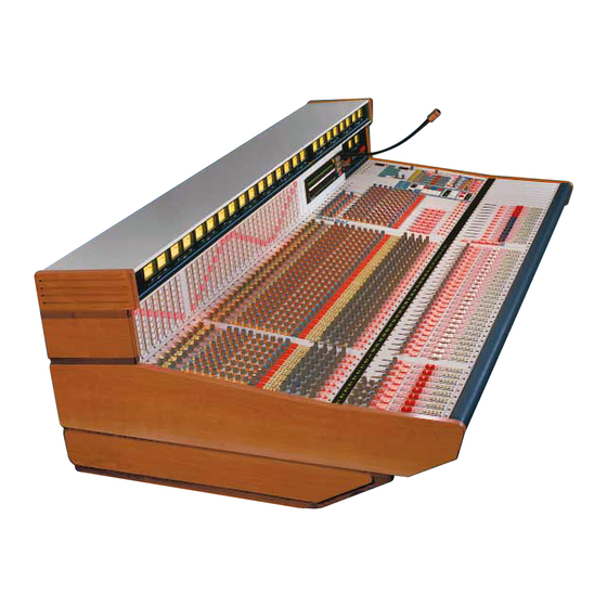
- Page 1 TV-1000 Audio Console TECHNICAL MANUAL 600 Industrial Drive, New Bern, North Carolina, USA 28562...
- Page 2 TV-1000 Live Television Audio Console Technical Manual - 2nd Edition (revised) TV-1000 Live Television Audio Console Technical Manual - 2nd Edition (revised) TV-1000 Live Television Audio Console Technical Manual - 2nd Edition (revised) ©1998 Wheatstone Corporation WHEATSTONE CORPORATION 600 Industrial Drive...
- Page 3 Addenda IMPORTANT: Please note the following updates to this technical manual: ROUTER CONTROLLER RACKMOUNT POWER SUPPLY SCHEMATIC & PARTS LIST (PCS-125): Slow Blow Fuse F1 is now 1.25AMP. SMART SELECT CAGE (mono switcher card) SCHEMATIC & PARTS LIST (SS-MI-8S): Regulator Q1 has been changed to a PQ05 SZ1 5V 1A. Resistors R1-R9 are now 619 OHM 1% .25W.
- Page 4 I N S E R T P O I N T S H I P P I N G S H E E T A T T E N T I O N ! Signal Path Insert Points This TV-1000 audio console is equipped with insert patch points on the following modules: Submasters AUX master signals...
- Page 5 D U A L F A I L S A F E P O W E R S U P P L I E S AT T E N T I O N ! Dual Redundant Power Supplies If your Wheatstone audio console has been ordered and shipped with a failsafe power supply system, it uses TWO separate rackmount power supplies. Though...
- Page 6 POWER SUPPLY AND SMART SELECT INSTALLATION GUIDE MAIN CONSOLE POWER PWR IN 1A PSC-1000 PSC-1000's connect to the PWR IN 1B Power Interface Module PWR-1000 PWR IN 2A PSC-1000 PWR IN 2B SMART SELECT RCC / BUTTON POWER PWR IN 1 PSC-125 #1 PSC-125's connect to the optional RCC-1000 or the...
- Page 7 E X T R A C T O R T O O L S Module Removal Tools Your Wheatstone TV-1000 audio console is equipped with two "module extractor tools" which are mounted underneath the console armrest, to the far right (just in front of the operator’s mainframe headphone jack).
-
Page 8: Table Of Contents
C O N T E N T S Table of Contents Chapter 1 — Installation Console Placement ..............1-2 Factory Leg Support System ............ 1-2 System Ground ................1-2 Power Supplies ................1-4 Failsafe Dual Redundant Supply ................1-5 Energizing the Supplies ..................1-5 Audio and Control Wiring ............ - Page 9 C O N T E N T S EFS On/Off ......................2-12 Machine Start and Stop ..................2-12 Cough ........................2-12 Talkback to Control Room ..................2-12 Input Module Logic Programming .......... 2-13 Mute/Tally ......................2-13 Cue Dropout ......................2-13 Timer Restart ......................
- Page 10 C O N T E N T S Cue and Solo ......................2-20 Direct Out ......................2-20 Preselector Panel ..............2-20 Input Fader Panel ..............2-21 Fader ........................2-21 Mute Groups ......................2-21 Mix Minus ......................2-21 Ready LED ......................2-21 Channel ON ......................
- Page 11 C O N T E N T S MI-1000 switchcard PCB (“SISW-1000”) ............TD-35 FPI-1000 fader panel main PCB ................ TD-46 Schematics (TECHNICAL DRAWINGS booklet) MI-1000 main PCB .................... TD-23 MI-1000 switchcard PCB (“SISW-1000”) ............TD-31 FPI-1000 fader panel main PCB ................ TD-46 Chapter 2 —...
- Page 12 C O N T E N T S Input Module Audio Wiring ............. 2-40 I/O Pinout Drawing ....................2-41 Parts Lists (located in Chapter 10) SI-1000 module ....................10-35 main card (SI-1000) ..................10-37 switch card (SISW-1000) ................10-39 Fader panel ......................10-23 main card (FPI-1000) ...................
- Page 13 C O N T E N T S Submaster Module Internal Programming ....... 3-6 AUX Solo ........................ 3-6 AUX Insert Bypass ....................3-6 Mix Minus Solo ....................... 3-7 Submaster Insert Bypass ..................3-7 Mix Minus ........................ 3-7 Sum LED VU ......................3-7 AUX Sends ......................
- Page 14 C O N T E N T S Fader Panel Controls ..............4-5 Insert Point ......................4-5 Fader ........................4-5 Mix Minus Assign (optional) ..................4-5 Channel ON ......................4-5 Sum VU ........................4-5 Mute Group Assign ....................4-5 Metering ..................4-6 Stereo Masters .......................
- Page 15 C O N T E N T S Chapter 5 — Control Room Monitor Module General ..................5-2 Controls ..................5-2 VU Trims ......................... 5-2 Solo/Cue/External Cue ................... 5-2 Monitor Select ......................5-2 Headphone Section ....................5-3 CR Section ......................5-3 Mode Switch ......................
- Page 16 C O N T E N T S Chapter 6 — Studio Monitor Module General ..................6-2 Controls ..................6-2 Studio VU Trims ...................... 6-2 Talkback Dim Trims ....................6-2 Monitor Select ......................6-2 Headphone Section ....................6-3 Studio Section ......................6-3 Mode Switch ......................
- Page 17 C O N T E N T S VO Module Input/Output Wiring ..........7-4 I/O Pinout Drawing ....................7-5 Parts Lists (located in Chapter 10) VO-1000 module ....................10-84 Main card (MO-1000) ..................10-86 Switch card (MOSW-1000) ................. 10-89 Timer control card (TCS-60) ................10-90 Printed Circuit Board Load Sheets (TECHNICAL DRAWINGS Booklet) MO-1000 main PCB ..................
- Page 18 C O N T E N T S ® Smart Select Cage ..............8-5 Smart Select Audio Wiring ..................8-5 Audio Connector Pinouts (stereo line) ..............8-7 Audio Connector Pinouts (mono mic/line) .............. 8-8 Parts Lists (located in Chapter 10) Rackmount unit (includes SS-MB-1 PCB) ...........
- Page 19 C O N T E N T S Parts Lists (located in Chapter 10) Rackmount unit .................... 10-10 Main PCB (PS-410) ..................10-12 Alarm PCB (PSA-1000) ................10-13 Printed Circuit Board Load Sheets (TECHNICAL DRAWINGS booklet) PS-410 main PCB ..................TD-128 PSA-1000 alarm PCB ................
- Page 20 C O N T E N T S Mono Mic/Line Input Module MI-1000 module ..................10-27 main card (MI-1000) ................10-29 switch card (SISW-1000) ..............10-32 Stereo Line Input Module SI-1000 module ..................10-35 main card (SI-1000) ................10-37 switch card (SISW-1000) ..............10-39 Input Preselector Overbridge panel (SB-1000) ..............
- Page 21 C O N T E N T S Power Interface Module PWR-1000 module ..................10-92 Mute Master Mute Master panel ..................10-93 Smart Select Cage Rackmount unit ..................10-94 Stereo Line switcher card (SS-SI-8) ............10-95 Mono Mic/Line switcher card (SS-MI-8) ............ 10-96 Controller card (SS-C-1A) ................
- Page 22 M A I N F R A M E I N S T A L L A T I O N Installation Chapter Contents Console Placement ..............1-2 Factory Leg Support System ............ 1-2 System Ground ................1-2 Power Supplies ................1-4 Failsafe Dual Redundant Supply ................
-
Page 23: Console Placement
M A I N F R A M E I N S T A L L A T I O N Installation Console Placement TV-1000 consoles are HEAVY. A fully loaded 70 position main- frame can easily weigh 600 to 700 lbs. We recommend using at least six people to move and place the console. - Page 24 M A I N F R A M E I N S T A L L A T I O N MIC PANEL EFFECTS RACK DEVICE 1 CONSOLE DEVICE 2 2-TRACK etc. DEVICE N MULTI-TRACK Tie the console ground lug terminal strip to the system earth ground.
-
Page 25: Power Supplies
(such as phono preamps, tape recorders, etc.) too near the rackmount supplies, to avoid magnetic interference into that equipment. If the optional Wheatstone FC-4 fan unit has been ordered, install and connect that to the PSC-1000 supply per the information given on pages 9-3 and 9-4. -
Page 26: Failsafe Dual Redundant Supply
(See previous section, "System Ground".) Failsafe Dual Redundant Supply Wheatstone failsafe power supply systems use two separate rack- mount power supplies for each piece of powered equipment. Though either is capable of running a full load on its own, in failsafe operation both units run in tandem: if one fails, the other takes over, assuring uninterrupted operation. -
Page 27: Audio And Control Wiring
Router Control Computer at its separate keyboard. The monitor screen should light up, run through built-in diagnostics, and eventually display the Main Menu described in the Wheatstone Router Control System manual. It is best to energize the TV-1000 console, console event computer, and rackmount smart select cage prior to booting up the PC event computer;... -
Page 28: Connection Procedures
M A I N F R A M E I N S T A L L A T I O N is made. Once released, the multipin connector held in the tool's jaw automatically indexes to the next connector pin. The technology is such that no stripping, soldering or tinning of wire ends is required;... -
Page 29: Insert Points
M A I N F R A M E I N S T A L L A T I O N Insert Points Certain module signals have built-in insert patch points in their signal NOTE it is also possible chains to allow outboard audio processing. These include SUBMASTERS to bridge the insert points at each module’s DB-25 (with both submaster and auxiliary master insert points) and STEREO... - Page 30 I N P U T S Input Modules Stereo Mic/Line Input General ..................2-5 Main Module ................2-6 Input section ......................2-6 AUX section ......................2-6 BAL/MIX Control - Mode Switch ................2-6 Bus Assign ......................2-7 Equalization section ....................2-7 Peak LED ........................
- Page 31 I N P U T S Parts Lists (located in Chapter 10) MLS-1000 module ....................10-15 main card (MLS-1000) ................. 10-17 switch card (MLSW-1000) ................10-19 Fader panel ......................10-23 main card (FPI-1000) ................... 10-24 switch card (FPSW-1000; optional) ............. 10-26 Printed Circuit Board Load Sheets (TECHNICAL DRAWINGS booklet) MLS-1000 main PCB ..................
- Page 32 I N P U T S Mono Mic/Line Input (continued) Input Module Logic Programming .......... 2-25 Mute/Tally ......................2-25 Cue Dropout ......................2-25 Timer Restart ......................2-26 Mix Minus ......................2-26 Bus Minus ® ..................................... 2-26 LED VU ladder ...................... 2-26 AUX sends ......................
- Page 33 I N P U T S Stereo Line Input (continued) Input Fader Panel ..............2-33 Fader ........................2-33 Mute Groups ......................2-33 Mix Minus ......................2-34 Ready LED ......................2-34 Channel ON ......................2-34 Bus Minus ® Foldback .................... 2-34 Metering ..................
-
Page 34: Chapter 2 - Stereo Mic/Line Inputs
S T E R E O M I C / L I N E I N P U T Ø Stereo Mic/Line Inputs S S S S T T T T E E E E R R R R E E E E O O O O LINE General MLS-1000 input modules accept and output stereo signals. -
Page 35: Main Module
S T E R E O M I C / L I N E I N P U T Ø Main Module Input section S S S S T T T T E E E E R R R R E E E E O O O O The upper section of the MLS input module selects between two LINE stereo microphone and two stereo line inputs. -
Page 36: Bus Assign
S T E R E O M I C / L I N E I N P U T Middle/Side Mode (M/S) — Intended for live or recorded signals Ø that utilize two monophonic microphones: one (feeding the module’s left channel) a cardioid mic directed along the main axis of the sound to be recorded;... -
Page 37: Preselector Panel
® Smart Select cage and Event Computer operation is covered in a separate technical manual (“The Wheatstone Router Control Sytstem”). V V V V U U U U Input Fader Panel MINUS Each input module has an associated fader panel located directly below it. -
Page 38: Mix Minus
S T E R E O M I C / L I N E I N P U T Mix Minus Feeds a summed version of the module’s signal to the console’s mix-minus system. Any module turned ON automatically feeds a signal to all eight mix-minus busses. -
Page 39: Metering
S T E R E O M I C / L I N E I N P U T Metering Each individual input channel has its own 7-segment mono sum LED VU ladder built in to that channel’s fader panel. This LED VU may be internally programmed to monitor pre or post fader. -
Page 40: Input Module External Control Ports
S T E R E O M I C / L I N E I N P U T Input Module External Control Ports The MLS-1000 input module may be turned on and off from a remote location by control wiring to the main module’s rear panel DB-9 “CONTROL”... -
Page 41: On Tally
S T E R E O M I C / L I N E I N P U T On Tally (Mic Function) This opto-isolated control function provides a continuous closure between CONTROL DB-9 pin 4 (ON TALLY) and pin 1 (GND) whenever the module’s channel ON switch is pressed. -
Page 42: Input Module Logic Programming
S T E R E O M I C / L I N E I N P U T Input Module Logic Programming Mute/Tally The console has four separate MUTE control lines; each input module may be programmed to activate any of these via its channel ON switch. The MUTE control lines are used to shut off control room and studio monitor speakers whenever the microphone for that particular location is activated. -
Page 43: Timer Restart
S T E R E O M I C / L I N E I N P U T Timer Restart Input modules may be programmed to automatically reset the console’s digital timer to zero and start it counting up whenever the channel On switch is pressed (this is the default setting). -
Page 44: Aux Sends
S T E R E O M I C / L I N E I N P U T AUX Sends The TV-1000 console aux SEND busses are normally configured as eight mono ACNs. However, they may be reprogrammed as left/ right pairs if desired. -
Page 45: Event Computer Start/Stop/Timer Enable
S T E R E O M I C / L I N E I N P U T Event Computer Start/Stop/Timer Enable When the TV-1000 console’s event computer takes a snapshot of switch settings on an input module, the channel ON switch state is included in the event storage. - Page 46 S T E R E O M I C / L I N E I N P U T I/O PORT "A" (Upper DB-25) MUTE FOLLOW (upper DB-9) Mates pin-for-pin to identical DB-9 mounted behind each overbridge preselector panel AUDIO COMMON (rear panel of console meterbridge) MIC 1 LT IN SH MIC 1 LT IN LO...
-
Page 47: General
M O N O M I C / L I N E I N P U T Ø LINE Mono Mic/Line Inputs INSERT General MI-1000 input modules accept and output mono signals. Each module can select one of four mono source signals: two are mic level and two are line level. -
Page 48: Main Module
M O N O M I C / L I N E I N P U T Ø Main Module Input section LINE The upper section of this input module selects between two mono INSERT microphone and two mono line inputs. The microphone section pro- vides a variable gain control, switched Mic 1 and Mic 2 -20dB pad circuits, and switchable +48V phantom power (labeled “V+”). -
Page 49: Cue And Solo
Note preselector panel switches can be programmed (through the Wheatstone RCC Event Computer’s separate keyboard and PRESELECTOR 3.5K monitor) to display 4-character alpha-numeric source codes that signify which source has been selected. -
Page 50: Input Fader Panel
M O N O M I C / L I N E I N P U T Input Fader Panel Each input module has an associated fader panel located directly below it. Starting from the bottom, these panels are configured as follows: FADER PANEL Fader... -
Page 51: Channel On
M O N O M I C / L I N E I N P U T Channel ON This momentary action lighted pushbutton switch turns the input channel on and off. It may also be programmed to activate tallies and mutes (4) and timer restart;... -
Page 52: Input Module External Control Ports
M O N O M I C / L I N E I N P U T Input Module Control Ports The MI-1000 input module has two control ports: one for micro- Refer to the pintout diagrams phone sources (“MIC LOGIC”), the other for line sources (“MA- on page 2-29 in conjunction with the text of this section. -
Page 53: On Tally
M O N O M I C / L I N E I N P U T On Tally Lets the module’s channel ON switch control an on-air light or other “microphone on” indicator at a remote location. This opto-isolated control function provides a continuous closure between pin 4 (ON TALLY) and pin 1 (GND) whenever the module’s channel ON switch is pressed. -
Page 54: Input Module Logic Programming
M O N O M I C / L I N E I N P U T Input Module Logic Programming Mute/Tally The console has four separate MUTE control lines; each input module may be programmed to activate any of these via its channel ON switch. -
Page 55: Timer Restart
M O N O M I C / L I N E I N P U T Timer Restart Input modules may be programmed to automatically reset the console’s digital timer to zero and start it counting up whenever the channel On switch is pressed (this is the default setting). -
Page 56: Aux Sends
M O N O M I C / L I N E I N P U T AUX Sends Aux sends may be programmed in pairs to follow the module’s channel ON switch regardless of their individual front panel pre/post fader switch settings (this is the default setting). -
Page 57: Mute Follow Connector
M O N O M I C / L I N E I N P U T Mute Follow Connector The module’s MUTE FOLLOW DB-9 connector, located at the top of the rear panel, is used to transmit muting and tally control signals between the module proper and it’s optional preselector panel in the console’s overbridge. - Page 58 M O N O M I C / L I N E I N P U T I/O PORT "A" (Upper DB-25) MUTE FOLLOW (upper DB-9) AUDIO COMMON MIC 1 IN SH MIC 1 IN LO MIC 1 IN HI MIC 2 IN SH MIC 2 IN LO MIC 2 IN HI...
-
Page 59: General
S T E R E O L I N E I N P U T Ø Stereo Line Inputs Ø General INSERT SI-1000 input modules accept and output stereo signals; each module can select one of four stereo line level source signals. Each input channel consists of three separate panels mounted in a single mainframe position: a) the main module itself (far right),... -
Page 60: Main Module
S T E R E O L I N E I N P U T Ø Ø Main Module Input section INSERT The upper section of this input module selects one of four stereo line inputs. The electronically balanced line input section has left and right center detent input gain controls (with PCB-mounted calibration trimpots for fine adjustment), left and right phase reverse switches and a patch point INSERT switch (stereo insert points are electronically... -
Page 61: Bus Assign
S T E R E O L I N E I N P U T module’s left channel) a cardioid mic directed along the main Ø axis of the sound to be recorded; the other a figure-eight mic Ø (feeding the module’s right channel) aligned at right angles to the cardioid pickup . -
Page 62: Preselector Panel
Note preselector panel switches can be programmed (through the Wheatstone RCC Event Computer’s separate keyboard and monitor) PRESELECTOR to display 4-character alpha-numeric source codes that signify which source has been selected. -
Page 63: Mix Minus
S T E R E O L I N E I N P U T Mix Minus Feeds the module’s signal to the console’s mix-minus system. Any module turned ON automatically feeds a signal to all eight mix-minus busses. Creation of a feed for IFB or remote use is done by simply pressing one or more of the eight mix-minus switches on the chosen input module’s fader panel, which removes that module's feed from the selected busses. -
Page 64: Metering
S T E R E O L I N E I N P U T Metering Each individual input channel has its own 7-segment LED sum VU ladder built in to that channel’s fader panel. This LED VU may be internally programmed to monitor pre or post fader. -
Page 65: Input Module Control Port
S T E R E O L I N E I N P U T Input Module Control Port The SI-1000 input module has one DB-9 CONTROL port mounted at Refer to the pinout dia- the bottom of the module’s rear panel. grams on page 2-41 in conjunction with the text Control functions are input specific;... -
Page 66: Input Module Logic Programming
S T E R E O L I N E I N P U T Input Module Logic Programming Mute/Tally The console has four separate MUTE control lines; each input module may be programmed to activate any of these via its channel ON switch. -
Page 67: Timer Restart
S T E R E O L I N E I N P U T Timer Restart Input modules may be programmed to automatically reset the console’s digital timer to zero and start it counting up whenever the channel On switch is pressed (this is the default setting). This is accomplished by PCB-mounted slide switch “SW23”. -
Page 68: Aux Sends
S T E R E O L I N E I N P U T AUX Sends The TV-1000 console aux SEND busses are normally configured as eight mono ACNs. However, they may be reprogrammed as left/right pairs if desired. This is accomplished by PCB-mounted slide switches on the module’s main PCB (SW 14-21). -
Page 69: Event Computer Start/Stop/Timer Enable
S T E R E O L I N E I N P U T Event Computer Start/Stop/Timer Enable When the TV-1000 console’s event computer takes a snapshot of switch settings on an input module, the channel ON switch state is included in the event storage. - Page 70 S T E R E O L I N E I N P U T I/O PORT "A" (Upper DB-25) MUTE FOLLOW (upper DB-9) AUDIO COMMON LINE 1 LT IN SH LINE 1 LT IN LO LINE 1 LT IN HI LINE 1 RT IN SH LINE 1 RT IN LO LINE 1 RT IN HI...
-
Page 71: I/O Pinout Drawing
S U B M A S T E R S Submaster Modules Chapter Contents General ..................3-3 Main Module Controls ..............3-3 Aux Master Section ....................3-3 Mix Minus Master Section ..................3-3 Mix Minus Confidence Feed ................... 3-4 Vu Trims ........................3-4 Aux Section ...................... -
Page 72: Parts Lists (Located In Chapter 10)
S U B M A S T E R S Parts Lists (located in Chapter 10) SUB-1000 module ....................10-45 Main card (SG-1000) ................... 10-47 Switch card (SGSW-1000) ................10-50 Confidence feed card (SGCF-1000) ............10-53 Fader panel ......................10-54 main card (FPO-1000) ................. -
Page 73: General
S U B M A S T E R S SOLO Submaster Module General TV-1000 audio consoles come equipped with eight stereo SUBMASTER modules. Each submaster module controls one stereo subgroup and houses the master circuitry for one console AUX SEND output and one console MIX MINUS output. There is an associated fader panel directly beneath each main module faceplate. -
Page 74: Mix Minus Confidence Feed
S U B M A S T E R S Mix Minus Confidence Feed SOLO This is a feature that interrupts regular Mix Minus outputs with a mono line level signal inputted at each submaster module’s rear panel upper DB-25 (“A”) audio connector. Individual interrupts are con- trolled by eight MIX MINUS CONFIDENCE FEED switches on a separate module. -
Page 75: Solo And Cue
S U B M A S T E R S SOLO Solo and Cue Both pre-fader CUE and post-fader SOLO switches are provided. These switches tap the module’s PFL and AFL signals and route them to the console’s stereo SOLO/CUE monitor bus, where they may be used to feed operator headphones, control room monitors, dedicated speakers, etc. -
Page 76: Metering
S U B M A S T E R S Mute Group Assign SOLO Each submaster module may be assigned to any or all of four Mute Control Groups. These groups (A thru D) can then be muted by the press of a single master mute button (in other words, whenever the master switch for a mute group is activated, any module assigned to that group will have its output muted). -
Page 77: Mix Minus Solo
S U B M A S T E R S Mix Minus Solo The module’s MXM signal is mono; the console’s SOLO circuit is stereo. PCB dipswitch “SW16” positions 3 (LT) and 4 (RT) (see Technical Drawings SG-1000 schematic page 58 B-3, and PCB load sheet page 60 extreme lower right) determines whether the mono MXM signal goes onto the left and/or right SOLO busses. -
Page 78: Cue Dropout
S U B M A S T E R S Note the preceding switches are reached through access cutouts in the module’s upper switchcard PCB. Aux send pairs may also be programmed to follow the module’s channel ON switch regardless of their individual front panel pre/post fader switch settings (this is the default setting). - Page 79 S U B M A S T E R S I/O PORT "A" (Upper DB-25) AUDIO COMMON SUB LT OUT SH SUB LT OUT LO SUB LT OUT HI SUB RT OUT SH SUB RT OUT LO SUB RT OUT HI AUX OUT SH AUX OUT LO AUX OUT HI...
- Page 80 S T E R E O M A S T E R S Stereo Master Modules Chapter Contents General ..................4-3 Main Module Controls ..............4-3 Vu Trims ........................4-3 Aux Section ......................4-3 Balance Pot ......................4-4 Master Assign ......................4-4 Outputs ........................
- Page 81 S T E R E O M A S T E R S Printed Circuit Board Load Sheets (TECHNICAL DRAWINGS booklet) SG-1000 main PCB ................... TD-60 SGSW-1000 switchcard PCB ................TD-65 SGCF-1000 tone interrupt PCB ................. TD-71 FPO-1000 fader panel main PCB ..............TD-75 FPSW-1000 fader panel switchcard PCB ............
-
Page 82: General
MSTR S T E R E O M A S T E R S MONO VU TRIMS MASTER Stereo Master Module General TV-1000 audio consoles come equipped with four stereo MASTER modules. Each master module controls one of the console’s main stereo outputs. There is an associated fader panel directly beneath each main module faceplate. -
Page 83: Balance Pot
MSTR S T E R E O M A S T E R S MONO Balance Pot VU TRIMS Controls the left/right stereo master signal. MASTER Master 1 & 2 Assign (Modules 3 & 4 only) Master module signals 3 & 4 may be back-assigned to Masters 1 & 2 for grand mastering situations. -
Page 84: Fader Panel Controls
S T E R E O M A S T E R S Fader Panel Controls Each stereo master module has an associated fader panel located directly below it. Starting from the bottom, these panels are configured as follows: FADER PANEL Fader A 3000 Series Penny &... -
Page 85: Metering
S T E R E O M A S T E R S Metering Stereo Masters Like inputs and submasters, stereo master fader panels have built- in mono sum LED VU ladders with PCB-mounted calibration trimpots. They may also be metered (PFL or AFL) at the stereo SOLO meter. However, they additionally have dedicated L-R VU meter pairs in the console’s meterbridge (these are calibrated by recessed trimpots at the top of each stereo master module faceplate). -
Page 86: Aux Sends
S T E R E O M A S T E R S AUX Sends The TV-1000 console aux send busses are normally configured as eight mono ACNs. However, they may be programmed as left/right pairs if desired. This is accomplished by PCB-mounted slide switches on the module’s main PCB (SW 7-14). -
Page 87: Master Module Input/Output Wiring
S T E R E O M A S T E R S Master Module Input/Output Wiring All wiring for the master modules is via two rear panel DB-25 connectors (see right). Signals include stereo and mono sum master outputs, external tone in, external tone control lines (upper connector “A”) and master insert points (lower connector “B”). - Page 88 S T E R E O M A S T E R S I/O PORT "A" (Upper DB-25) LINE OUT LT SH LINE OUT LT LO LINE OUT LT HI LINE OUT RT SH LINE OUT RT LO LINE OUT RT HI STEREO 1 OUT LT SH STEREO 1 OUT LT LO STEREO 1 OUT LT HI...
- Page 89 S T E R E O M A S T E R S I/O PORT "A" (Upper DB-25) STEREO LT OUT SH STEREO LT OUT LO STEREO LT OUT HI STEREO RT OUT SH STEREO RT OUT LO STEREO RT OUT HI SPARE MONO PRE OUT SH MONO PRE OUT LO...
- Page 90 C O N T R O L R O O M Control Room Module Chapter Contents General ..................5-2 Controls ..................5-2 VU Trims ......................... 5-2 Solo/Cue/External Cue ................... 5-2 Monitor Select ......................5-2 Headphone Section ....................5-3 CR Section ......................5-3 Mode Switch ......................
-
Page 91: Controls
C O N T R O L R O O M Control Room Module SOLO/CUE General TV-1000 audio consoles are equipped with a CR-1000 control room monitor module. The control room module allows the console operator to monitor the TV-1000 console’s inputs and outputs by means of a monitor source select switchbank and the console’s SOLO/CUE sys- tem. -
Page 92: Headphone Section
C O N T R O L R O O M Headphone Section The module’s headphone circuit follows the monitor source select switching. There are two headphone outputs: one electronically bal- anced line level out (programmable as either pre or post HDPN level control), and the other driven by a built-in amplifier (amplifier output SOLO/CUE may be stereo or L+R summed). -
Page 93: Solo/Cue Logic Programming
C O N T R O L R O O M When solo/cue is de-activated (either by pressing the pertinent switch again, or by using the master solo/cue dropout panel switch) the meters return to the selected external signal. Since SOLO (AFL) and CUE (PFL) functions are normally programmed to interrupt control room and operator headphone monitor feeds, and since there can easily be over one hundred individual solo and cue switches scattered throughout an average console’s control surface, the SOLO/CUE... -
Page 94: Cr/Hdpn Dim
C O N T R O L R O O M CR/HDPN Dim Option Normally a cue or solo signal will replace the CR-1000 module’s regular monitor output. However, it is also possible to DIM (attenuate) the regular output and overlay it with the full strength cue/solo signal. PCB dipswitch “SW24”... - Page 95 C O N T R O L R O O M Control Room “On-Air” Tally Port The CR-1000 module tally port is activated by the console’s mute control lines (see dipswitch “SW22”, preceding). Tally DIG COMMON signals outputted module’s DB-9 DIG COMMON “TALLIES”...
- Page 96 C O N T R O L R O O M I/O PORT "A" (Upper DB-25) AUDIO COMMON EXT 1 LT IN SH EXT 1 LT IN LO EXT 1 LT IN HI EXT 1 RT IN SH EXT 1 RT IN LO EXT 1 RT IN HI EXT 2 LT IN SH EXT 2 LT IN LO...
-
Page 97: Hdpn Amp Output Mode
S T U D I O C O N T R O L Studio Control Module Chapter Contents General ..................6-2 Controls ..................6-2 Studio VU Trims ...................... 6-2 Talkback Dim Trims ....................6-2 Monitor Select ......................6-2 Headphone Section ....................6-3 Studio Section ...................... -
Page 98: General
S T U D I O C O N T R O L Studio Control Module STUDIO General HDPN TV-1000 audio consoles can be equipped with one or more STUDIO TB SC-1000 studio monitor modules. Each of these modules allows the console operator send... -
Page 99: Headphone Section
S T U D I O C O N T R O L STUDIO HDPN STUDIO TB Headphone Section The studio module’s headphone circuit follows the monitor source select switching. There are two headphone outputs: one electronically balanced line level out (programmable as either pre or post HDPN level control), and the other driven by a built-in amplifier (amplifier output may be stereo or L+R summed). -
Page 100: Studio Module Logic Programming
S T U D I O C O N T R O L Studio Module Logic Programming HDPN Talkback Interrupt PCB dipswitch “SW25” (dipswitch toggle #4; see Technical Draw- ings CR-1000 schematic page 87 C-4, and PCB load sheet page 89 lower right) determines whether talkback will interrupt the studio HDPN outputs. -
Page 101: Studio "On-Air" Tally Port
S T U D I O C O N T R O L TALLIES Studio Tally Port (DB-9) The SC-1000 module tally port is activated by the console’s mute control lines (see dipswitch “SW22”, preceding). Tally DIG COMMON signals are outputted at the module’s DB-9 “TALLIES” DIG COMMON connector, located at the top of the module’s rear panel. - Page 102 S T U D I O C O N T R O L I/O PORT "A" (Upper DB-25) AUDIO COMMON EXT 1 LT IN SH EXT 1 LT IN LO EXT 1 LT IN HI EXT 1 RT IN SH EXT 1 RT IN LO EXT 1 RT IN HI EXT 2 LT IN SH...
- Page 103 V U / O S C I L L A T O R VU / Oscillator Module Chapter Contents General ..................7-2 Module Controls ................. 7-2 External Oscillator Enable ..................7-2 VU Trims ......................... 7-2 Talkback ........................7-3 External Meter Select ..................... 7-3 Oscillator Section ....................
-
Page 104: General
V U / O S C I L L A T O R ENABLE SOLO/EXT SPARE VU / Oscillator Module General The TV-1000 audio console VU/Oscillator (VO) module houses the console’s talkback, oscillator, external meter and timer control circuits. LOWER PANEL EXTERNAL A control panel directly below the main module houses a METER SELECT... -
Page 105: Talkback
V U / O S C I L L A T O R Talkback ENABLE The master level control for the console operator’s talkback microphone. The signal comes from the associated front panel XLR SOLO/EXT input jack OR the module’s external talkback input pins on the rear panel upper DB-9 (“TB/OSC”) connector. -
Page 106: Vo Module Input/Output Wiring
V U / O S C I L L A T O R VO Module Input/Output Wiring All wiring for the VO module is via two DB-25 and two DB-9 connectors mounted on the module’s rear panel (see right). See pinout drawing on next page for complete wiring details. Parts Lists VO-1000 control room module parts lists may be found in Chapter 10. -
Page 107: Timer
V U / O S C I L L A T O R I/O PORT "A" (Upper DB-25) AUDIO COMMON EXT 1 LT IN SH (DB-9) EXT 1 LT IN LO EXT 1 LT IN HI EXT 1 RT IN SH EXT 1 RT IN LO EXT 1 RT IN HI EXT 2 LT IN SH... - Page 108 O P T I O N S Options Chapter Contents RCC Event Computer ..............8-3 Event Computer Wiring ..................... 8-4 Parts Lists (located in Chapter 10) System access panel (RCC-1000) .............. 10-100 Switch controller card (DSC-1000) .............. 10-102 Buffer card (RBUF-6A) ................. 10-104 Display strip card (DISP-8) ................
- Page 109 O P T I O N S Confidence Module ..............8-9 Mix-Minus Interrupt ....................8-9 Stereo Master 1 Interrupt ..................8-9 External Control ...................... 8-10 Internal Programming Options ................8-10 Confidence Module Wiring Diagram ............... 8-11 Confidence Module Pinout Drawing ............... 8-13 Parts List (located in Chapter 10) ...............
- Page 110 O P T I O N S RCC Event Computer The Wheatstone TV-1000 RCC Event Computer is a PC-based system that takes snapshots of all console audio switching (exceptions: solo/cue, talkback, and oscillator settings), saves them under an event name, and recalls them for instant implementation via a control panel (the Event Computer Access Panel) mounted to the right of the console’s studio monitor modules.
- Page 111 O P T I O N S Event Computer Wiring The back of the console’s event computer access panel interfaces to three locations: 1) One DB-9 “serial control” connector runs, via special cable, to a matching DB-9 “I/O” connector on the back of the rackmounted Smart Select Cage (see photo below; there are two such connectors—they are interchangeable;...
-
Page 112: Smart Select Cage
“TV-1000 Power Systems” chapter of this manual (page 9-7). Audio wiring for the cage is discussed in the separate “Wheatstone Router Control System” manual. Pinout diagrams are also reproduced on pages 8-7 and 8-8 of this chapter. - Page 113 ® SMART SELECT System The Wheatstone Smart Select Cage – It is 8 3/4” high and occupies five rackmount spaces Rear view of the chassis showing audio connectors for eighteen preselector panels page 8 – 6 TV1 / May 98...
-
Page 114: Stereo Line Switcher Card (Ss-Si-8)
O P T I O N S U p p e r D B - 2 5 F u n c t i o n Channel 1 LT shield Channel 1 LT low Channel 1 LT high Channel 1 RT shield Channel 1 RT low Channel 1 RT high Channel 2 LT shield... - Page 115 O P T I O N S Upper DB-25 Function Channel 1 shield Channel 1 low Channel 1 high Channel 2 shield Channel 2 low Channel 2 high Channel 3 shield Channel 3 low Channel 3 high Channel 4 shield Mono Mic/Line Module Channel 4 low Upper DB-25 Female...
-
Page 116: Mix-Minus Interrupt
CONF O P T I O N S Confidence Module The CONF-1000 Confidence module is designed to interrupt regular console signals with a substitute signal as desired. It affects MIX-MINUS and STEREO MASTER #1 LINE OUT signals. Mix-Minus Interrupt (Confidence Feed) By their nature, mix-minus outputs are normally only active for those short periods of time when they are in actual use;... -
Page 117: External Control
CONF O P T I O N S Confidence Module External Control The Stereo Master 1 Interrupt function can be de-activated from a remote location via a user-supplied switch. Simply provide a momen- tary closure between Lower DB-25 connector Pin 17 (Remote Tone Dropout Logic) and Pin 5 (digital ground). - Page 118 O P T I O N S UPPER DB-25 Connector Pin on Confidence Feed UPPER DB-25 Module Connector Pin on: Mix Minus Submaster Interrupt Logic 1 Module 1 Mix Minus Submaster Interrupt Logic 2 Module 2 Mix Minus Submaster Interrupt Logic 3 Module 3 Mix Minus Submaster...
- Page 119 O P T I O N S Confidence Module Control Wiring to Submasters & Stereo Master #1 STEREO MASTER #1 INTERRUPT CONTROL WIRING ("Tone Interrupt") Connect Confidence Feed module upper DB-25 control pin 17 (Stereo Master 1 interrupt logic) to upper DB-25 pin 17 of Stereo Master Module #1 (Tone Interrupt Logic) UPPER DB-25 UPPER DB-25 Connector Pin on...
- Page 120 O P T I O N S I/O PORT "A" (Upper DB-25) AUDIO COMMON DIGITAL GND MXM 1 INTERRUPT LOGIC MXM 2 INTERRUPT LOGIC DIGITAL GND MXM 3 INTERRUPT LOGIC MXM 4 INTERRUPT LOGIC DIGITAL GND MXM 5 INTERRUPT LOGIC MXM 6 INTERRUPT LOGIC DIGITAL GND MXM 7 INTERRUPT LOGIC...
-
Page 121: Studio Mute Link
O P T I O N S Mute Master Panel The MUTE MASTER panel handles two functions: (1) it houses the console’s four mute group (A thru D) master switches, and (2) it contains the master switch for the console’s STUDIO MUTE LINK feature. -
Page 122: Tape Remote Panel
O P T I O N S Tape Remote Panel This optional panel is used to control three external source machines using three pairs of START/STOP buttons. LED indicators in each switch function as tallyback indicators and are powered by the source machines; there are no internal connections between the tape remote panel and the console’s power rails. -
Page 123: Timer
O P T I O N S ENABLE SOLO/EXT LINE Timer The timer display is also mounted above the RCC Event Computer, just to the right of the clock. It is controlled by four pushbutton switches at the bottom of the VU/Oscillator module. Control functions are as follows: AUTO –... -
Page 124: Schematic (Technical Drawings Booklet
T V - 1 0 0 0 P O W E R S Y S T E M S TV-1000 Power Systems Chapter Contents General ..................9-2 PSC-1000 Console Power Supply ..........9-2 Alarm Circuit ......................9-3 Thermal Protection ....................9-3 Rear Panel Wiring and Pinouts ................ -
Page 125: General
T V - 1 0 0 0 P O W E R S Y S T E M S TV-1000 Power Systems General TV-1000 audio consoles utilize three separate power supply systems; in each case a separate rackmounted unit supplies power via special cables outfitted with 10-pin connectors at both ends. -
Page 126: Alarm Circuit
ALARM connector. This closure is designed to page. activate an optional Wheatstone Model FC-4 rackmount fan unit which brings the supply back down to an acceptable temperature by forcing air past the power supply’s external heatsink fins. - Page 127 TV-1000 console’s power interface module (see page 9-5. AC IN ALARM CONNECTOR: THERMAL switch pins are used to control an op- THERMAL SW COMMON tional Wheatstone Model FC-4 ALARM rackmount fan unit. EXTERNAL ALARM THERMAL SW N.O. CONNECTOR pins send a relay closure (maximum rating 1 amp @125VAC;...
- Page 128 T V - 1 0 0 0 P O W E R S Y S T E M S Power Interface Module The PWR-1000 power interface module accepts power from the console’s (dual failsafe) rackmounted PSC-1000 power supplies and feeds it to the TV-1000 console. In the unlikely event of a power supply failure, the panel automatically switches over to the second redundant supply so the console continues uninterrupted operation.
- Page 129 T V - 1 0 0 0 P O W E R S Y S T E M S PSC-125 Event Computer Power Supply This two rack space unit (total height 3-1/2”) powers the TV-1000’s Event Computer access panel. It draws about 1.5 amps and has no special rackmount requirements. It has two front panel status LEDs: +D (5V) and LAMP (12V).
- Page 130 T V - 1 0 0 0 P O W E R S Y S T E M S PSC-340 Smart Select Cage Power Supply This three rack space unit (total height 5-1/4”) powers the TV-1000’s separate rackmounted Smart Select® Cage, which performs the actual audio switching for the console’s input module preselector panels.
- Page 131 T V - 1 0 0 0 P O W E R S Y S T E M S ordered a failsafe configuration, there will be two supplies; each feeds one connector on the back of the cage. A schematic may be found on page 167 of the Technical Drawings;...
- Page 132 P A R T L I S T S TV-1000 Part Lists Chapter Contents Console Mainframe Mainframe (typical, 71-Position) ..............10-3 Main module motherboards (MBM-1000)............ 10-5 Fader panel motherboards (MBF-1000) ............10-6 Preselector panel motherboards (MBS-1000)..........10-7 Meter LED lamp card (LED-3) ..............10-8 Extender module service card (EXT-1000) ..........
- Page 133 P A R T L I S T S switch card (FPSW-1000) ..............10-57 Stereo Master Module MSTR-1000 module................... 10-58 Main card (SG-1000) ................. 10-60 Switch card (SGSW-1000)................. 10-63 Confidence feed card (SGCF-1000)............10-66 Fader panel ....................10-67 main card (FPI-1000) ................10-68 switch card (FPSW-1000) ..............
- Page 134 P A R T L I S T S MAINFRAME (TYPICAL 71 POSITION) DESCRIPTION QTY WS P/N COMPONENT NO. SIDEPLATE_LEFT CHERRY 100052 SIDEPLATE_RIGHT CHERRY 100053 LEG_SET_TV1000 140110 END CONNECTORS FOR POWER CABLE FROM EVENT COMPUTER PANEL TO METERBRIDGE SBM-1000 SMART CONN_DB_15 200014 BUTTON PCB POWER CONNECTOR SOCKET...
- Page 135 P A R T L I S T S MAINFRAME (TYPICAL 71 POSITION) DESCRIPTION QTY WS P/N COMPONENT NO. OPERATOR HEADPHONE RTS OUTPUT JACK JACK_J112 260005 (UNDERNEATH CONSOLE ARMREST, FAR RIGHT) CLOCK CONNECTOR, MIDDLE REAR OF METERBRIDGE, SOCKET_BNC 260016 LEITCH MASTER CLOCK SYNC FEED RIBBON CABLE RESTRAINTS PATCH_CLIPS 280000...
- Page 136 P A R T L I S T S MBM - 1000 PCB QTY WS P/N COMPONENT NO. DESCRIPTION CT6-CT13, CT26-CT33 CONN_CARDEDGE_120 PIN 220023 CT14, CT34 CONN_BOARD-TO-BOARD_120 PIN_MALE 220024 CT5, CT25 CONN_BOARD-TO-BOARD_120 PIN_FEMALE 220025 CT16 CONN_CARDEDGE_62_PIN 220027 CT17 CONN_BOARD-TO-BOARD_60 PIN_MALE 220074 CT15 CONN_BOARD-TO-BOARD_60 PIN_FEMALE...
- Page 137 P A R T L I S T S MBF - 1000 PCB QTY WS P/N COMPONENT NO. DESCRIPTION CT18-CT25 CONN_CARDEDGE_120 PIN 220023 CT26 CONN_BOARD-TO-BOARD_120 PIN_MALE 220024 CT17 CONN_BOARD-TO-BOARD_120 PIN_FEMALE 220025 CT1-CT16 HEADER_20_PIN_ST 250074 PCB_MBF1000 700268 Console Mainframe (fader panel motherboards) page 10 –...
- Page 138 P A R T L I S T S MBS - 1000 PCB QTY WS P/N COMPONENT NO. DESCRIPTION CT3-CT10 CONN_CARDEDGE_62_PIN 220027 CT11 CONN_BOARD-TO-BOARD_60 PIN_MALE 220074 CONN_BOARD-TO-BOARD_60 PIN_FEMALE 220075 CT12-CT20 CONN_DB9_AMP_PC MOUNT 250032 CONN_DB15_AMP_PC MOUNT 250076 PCB_MBS1000 700280 Console Mainframe (preselector panel motherboards) page 10 –...
- Page 139 P A R T L I S T S LED - 3 QTY WS P/N COMPONENT NO. DESCRIPTION Q1-Q5 TRANSISTOR_MMBTA05 NPN SMT 345001 C1, C2 CAPACITOR_.1µF 50V CERAMIC SMT 415007 R2-R4, R7 RESISTOR_3.3Ω_SMT_1206 435001 R5, R6, R8, R9 RESISTOR_39Ω_SMT_1206 435004 RESISTOR_1.00K_SMT_1206 435015 DS1-DS8...
- Page 140 P A R T L I S T S EXT - 1000 COMPONENT NO. DESCRIPTION QTY WS P/N CABLE_50 COND FLAT RIBBON 150007 EXT-120 PCB CONN_CARDEDGE_120 PIN 220023 MAIN PCB (EXT-1000): CT1-CT6 CONN_RIBBON_50_PIN_EXT 250030 EXT-120 PCB: 3 PER MAIN PCB (EXT-1000): CT1-CT6 STRAIN RELIEF_RIBBON CABLE 250031 EXT-120 PCB: 3 PER...
- Page 141 P A R T L I S T S PSC - 1000 COMPONENT NO. DESCRIPTION WS P/N PSC-600 POWER SUPPLY FACEPLATE 007085 PSC-600 POWER SUPPLY REAR 007086 PSC-600 POWER SUPPLY COVER 007087 PSC-600 POWER SUPPLY FRAME 007088 PSC-600 POWER SUPPLY FACEPLATE TRIM 007095 ON/OFF SWITCH PSC-600 POWER SUPPLY SWITCH BRACKET...
- Page 142 P A R T L I S T S PSC - 1000 QTY WS P/N COMPONENT NO. DESCRIPTION XFORMER_TV1000_NEW 800025 SCREWLOCK_FEMALE 820047 SCR_#6-32X1_1/4"PHI_PAN_MS_SS 820073 SCR_#10-32X1_HEX_MS_ZI 820074 SCR_#10-32X1/2_PHI_FL8_MS_ZI 820075 STUD_PEM_PS60_LUG 821013 WASHER_1/4_USS_F/L_ZI 822019 SPACER_THREAD_440X1/4 823016 STANDOFF_2" 823017 STANDOFF_LS50 823019 SPACER_ALUMINUM_FSI 823033 POWER SUPPLY HANDLE 824015 HEATSINK_PS410...
- Page 143 P A R T L I S T S PS-410 PCB COMPONENT NO. DESCRIPTION WS P/N LT PCB: Q4 REGULATOR_LM317_POSITIVE ADJUSTABLE 330012 LT PCB: Q1-Q3, Q5-Q7 REGULATOR_LT1083 7.5A POSITIVE ADJUSTABLE 330022 RT PCB: Q1-Q3, Q5-Q7 LT REAR HEATSINK, RT REAR HEATSINK BRIDGE RECTIFIER_MB3510 _35 AMP 1000 VOLT 350000 LT PCB: D3-D12...
- Page 144 P A R T L I S T S PS-410 PCB COMPONENT NO. DESCRIPTION WS P/N LT PCB: CR2 POT_TRIM_HOR_10K 500017 LT PCB: CR1, CR3 POT_TRIM_HOR_500Ω 500019 RT PCB: CR3 LT PCB: SW1 SWITCH_DIP_4_POS 510047 LT PCB: DS1, DS3, DS5 LED_L1200_GREEN 600003 RT PCB: DS4, DS6...
- Page 145 P A R T L I S T S PSA - 1000 PCB COMPONENT NO. DESCRIPTION WS P/N CONN_DB9_AMP_TV600 250032 HEADER_6_PIN_JST 250065 IC_74HC14 300053 IC_LM3909_LED FLASHER 320016 REGULATOR_LM2940 5V_LOW DROP OUT VOLTAGE 330017 U1, U2, U3 IC_LH1522AB DUAL FET OPTO COUPLER 340020 D1, D7-D14 DIODE_1N4002...
- Page 146 P A R T L I S T S PSR- 1000 PCB COMPONENT NO. DESCRIPTION WS P/N SOCKET_POWER 230006 D1, D2 DIODE_QCR6A4 350009 C1, C2 CAPACITOR_47UF_200V ELECTROLYTIC 400036 C3, C4 CAPACITOR_.0047µUF 1KV CERAMIC 410015 R7-R9 RESISTOR_3.3OHM_5W 430026 R1-R6 RESISTOR_22K_CARBON 430244 RELAY_AROMAT_24V_15A 550009 PCB_PSR1000...
- Page 147 P A R T L I S T S MLS - 1000 COMPONENT NO. DESCRIPTION WS P/N MLS-1000_FACEPLATE 004603 DUAL DB-25_DUAL DB-9 REAR PANEL - TV1000 004700 TR1, TR2 CAN_MIC 110028 LATCHING BLOCKS - .190 200011 CONN_DB_IDD9_HDF20 200031 CONN_R/A_PC_MT_9_MBLS 220016 CT6, CT15 CONN_R/A_PC_MT_25_PIN 220017...
- Page 148 P A R T L I S T S MLS - 1000 COMPONENT NO. DESCRIPTION WS P/N CR10, CR11 BOURNS_10KΩ QUAD CONDUCTIVE PLASTIC 500055 BOURNS_10KΩ DUAL CONDUCTIVE PLASTIC 500056 CR1-CR8 BOURNS_10KΩ SINGLE AUDIO CONDUCTIVE PLASTIC 500058 CR13-CR15 POT_10K_ 4/2 CONCENTRIC LINEAR 500060 CR16 POT_10K_4/4 CONCENTRIC LINEAR...
- Page 149 P A R T L I S T S MLS - 1000 PCB COMPONENT NO. DESCRIPTION WS P/N U1-U21, U23-U25, U36-U39, U42, U43, U45-U48, U52-U54, U56-U64, U66 SOCKET_SMT_JS8_PIN 245001 U90-U92 U40, U85-U89 SOCKET_SMT_JS14_PIN 245002 U22, U26-U35, U41, U44, U49-U51, U55, U67-U84 SOCKET_SMT_JS16_PIN 245003 CT5, CT7-CT12...
- Page 150 P A R T L I S T S MLS - 1000 PCB COMPONENT NO. DESCRIPTION WS P/N R393 RESISTOR_4.99K_PRECISION 430137 R308, R309, R312, R315, R379, R382, R385, R388 RESISTOR_10Ω_SMT_1206 435002 R24, R30, R36, R41, R47, R53 RESISTOR_100Ω_SMT_1206 435007 R31-R33, R51 RESISTOR_475Ω_SMT_1206 435011 R19-R21, R25-R27, R39, R45...
- Page 151 P A R T L I S T S MLSW - 1000 PCB COMPONENT NO. DESCRIPTION WS P/N TR1, TR2 CAN_MIC_TV1000 110028 U9, U18, U19, U78-U81, U92-U104 SOCKET_8 PIN_.3" DIP_SMT 245001 SOCKET_14 PIN_.3" DIP_SMT 245002 CT1-CT5, CT7, CT8 HEADER_3M_26_PIN_ST 250044 HEADER_10_PIN_ST 250077 IC_4066...
- Page 152 P A R T L I S T S MLSW - 1000 PCB COMPONENT NO. DESCRIPTION WS P/N REGULATOR_7812 POSITIVE_12V 330002 REGULATOR_7912 NEGATIVE_12 V 330007 Q22, Q23 REGULATOR_PQ05SZ1_5V_1A _SMT 335001 U78-U80, U92-U95, U97-U99, U101-U104 IC_LH1522AB DUAL FET_OPTO COUPLER 340020 Q1, Q6-Q13, Q19, Q24, Q25 TRANSISTOR_MMBTA05 NPN SMT 345001 Q2-Q5, Q14-Q18...
- Page 153 P A R T L I S T S MLSW - 1000 PCB COMPONENT NO. DESCRIPTION WS P/N J4, J9, R191-R206, R220-R227, R235-R242, R342 RESISTOR_3.3Ω_SMT_1206 435001 R228, R296, R305 RESISTOR_10Ω_SMT_1206 435002 R266, R267 RESISTOR_47Ω_SMT_1206 435005 R23, R89 RESISTOR_100Ω_SMT_1206 435007 R351, R381 RESISTOR_150Ω_SMT_1206 435008 R12, R15, R17, R56, R87, R176, R179, R346, R360, R376,...
- Page 154 P A R T L I S T S MLSW - 1000 PCB COMPONENT NO. DESCRIPTION WS P/N SW1-SW30 SWITCH_2 POLE PUSHBUTTON_ MOMENTARY 510113 SW31, SW32, SW35 SWITCH_DIP_4_POS _SMT 515001 SW33, SW34, SW36-SW42 SWITCH_SLIDE _SMT 515003 SW1-SW7, SW10-SW25, SW27-SW30 BUTTON_LUMA_230_WHT 530083 SW8, SW9 BUTTON_LUMA_230_RED...
- Page 155 P A R T L I S T S MLS - 1000 FADER PANEL COMPONENT NO. DESCRIPTION WS P/N STEREO IN FADER FACEPLATE 004616 CT2, CT7 PLUG_3_PIN_JST 230028 PLUG_6_PIN_JST 230031 PLUG_9_PIN_JST 230032 MAIN PCB: CT1, CT4 PLUG_RIBBON_14_PIN 250034 SWITCH PCB: CT1 HEADER_3_PIN_JST 250062 HEADER_6_PIN_JST...
- Page 156 P A R T L I S T S FPI - 1000 PCB COMPONENT NO. DESCRIPTION WS P/N U1, U16-U19 SOCKET_SMT_JS8_PIN 245001 SOCKET_SMT_JS20_PIN 245004 HEADER_3_PIN_JST 250062 HEADER_6_PIN_JST 250065 HEADER_9_PIN_JST 250066 CT1, CT4 HEADER_14_PIN_TV1000 250073 IC_74ACT08 TTL SMT 305006 IC_74ACT32 TTL SMT 305010 U3, U4, U6, U7, U9, U10 IC_74AC14 TTL SMT...
- Page 157 P A R T L I S T S FPI - 1000 PCB COMPONENT NO. DESCRIPTION WS P/N J1, J2, R38, R156 RESISTOR_3.3Ω_SMT_1206 435001 R100 RESISTOR_10Ω_SMT_1206 435002 R48-R51, R54, R69, R70, R188 RESISTOR_100Ω_SMT_1206 435007 R104 RESISTOR_220Ω_SMT_1206 435009 R5, R7, R9, R11, R13, R15, R17, R19, R21, R23, R25, R27, R30, R31, R33, R35, RESISTOR_619Ω_SMT_1206 435013...
- Page 158 P A R T L I S T S FPSW - 1000 PCB COMPONENT NO. DESCRIPTION WS P/N PLUG_RIBBON_14_PIN 250034 HEADER_14_PIN_TV1000 250073 R1-R5 RESISTOR_10Ω_SMT_1206 435002 SW1-SW4 SWITCH_2 POLE PUSHBUTTON_ MOMENTARY 510113 SW1-SW4 BUTTON_LUMA_230_YLW 530085 LED_YELLOW_SMT 605006 DS1-DS4 LED_R/A_YLW_SMT_HI_INTENSITY 605009 PCB_FPSW1000 700294 NUT_PEM_SP8 821012...
- Page 159 P A R T L I S T S MI-1000 COMPONENT NO. DESCRIPTION WS P/N TR1,TR2 CAN_MIC_TV1000 110028 LATCHING BLOCKS - .190 200011 "MACHINE CONTROL" CONNECTOR CONN_DB_IDD9_HDF20 200031 CT1, CT9 CONN_R/A_PC_MT_9_MBLS 220016 CONN_R/A_PC_MT_25_PIN 220017 SWITCH PCB (SISW-1000): CT5 PLUG_RIBBON_10_PIN 230020 MAIN PCB (MI-1000): CT3-CT8 SOCKET_26_PIN_PLUG 250043...
- Page 160 P A R T L I S T S MI-1000 COMPONENT NO. DESCRIPTION WS P/N CR13, CR14 BOURNS QUAD LINEAR 500055 BOURNS DUAL LINEAR, CDT 500056 CR1-CR8 BOURNS SINGLE AUDIO 500058 CR10-CR12 POT_GS10M 500059 CR16 POT_SA10Q 500061 CR17, CR18 POT_SA10Q 505002 MAIN PCB (MI-1000): SW1-SW12 SWITCH_2 POLE PUSHBUTTON _MOMENTARY...
- Page 161 P A R T L I S T S MI-1000 PCB COMPONENT NO. DESCRIPTION WS P/N U1-U20, U32, U37-U56, U59 SOCKET_SMT_JS8_PIN 245001 U33-U36, U57, U77-U79, U81 SOCKET_SMT_JS14_PIN 245002 U21-U31, U59-U76 SOCKET_SMT_JS16_PIN 245003 REGULATOR_PQ05SZ1 5V 1A SMT T/R 335001 Q1-Q10 TRANSISTOR_MMBTA05 NPN SMT 345001 Z1, Z2 DIODE_5.1V SMT ZENER C5V1...
- Page 162 P A R T L I S T S MI-1000 PCB COMPONENT NO. DESCRIPTION WS P/N R263 RESISTOR_4.99K_PRECISION 430137 RESISTOR_3.3Ω_SMT_1206 435001 R140, R254, R257, R260, R322, R325, R328, R331 RESISTOR_10Ω_SMT_1206 435002 R20, R25, R32 RESISTOR_100Ω_SMT_1206 435007 R110, R137 RESISTOR_150Ω_SMT_1206 435008 R194, R198, R339, R341, R343, R345 RESISTOR_220Ω_SMT_1206 435009...
- Page 163 P A R T L I S T S MI-1000 PCB COMPONENT NO. DESCRIPTION WS P/N CR17, CR18 POT_TRIM_HOR_10K_SMT 505002 SW1-SW12 SWITCH_2 POLE PUSHBUTTON_MOMENTARY 510113 SW15, SW16, SW18, SW19 SWITCH_DIP_4_POS _SMT 515001 SW13, SW14, SW17 SWITCH_SLIDE _SMT 515003 DS5, DS6, DS11, DS12 LED_R/A_RED_SMT_HI_INTENSITY 605008 DS1, DS2, DS7-DS10...
- Page 164 P A R T L I S T S SISW-1000 PCB COMPONENT NO. DESCRIPTION WS P/N U9,U15,U16,U77-U79,U81 SOCKET_SMT_JS8_PIN 245001 SOCKET_SMT_JS14_PIN 245002 CT1-CT4,CT6,CT7 SOCKET_26_PIN_PLUG 250043 CT1-CT4,CT6,CT7 HEADER_3M_26_PIN_ST 250044 HEADER_10_PIN_ST 250077 IC_4066 300005 U42, U44, U45, U49, U51, U53, U55, U56, U59, U63, U65, IC_74ABT244 TTL SMT 305002 U3-U5, U21, U32...
- Page 165 P A R T L I S T S SISW-1000 PCB COMPONENT NO. DESCRIPTION WS P/N C156, C157 CAPACITOR_10µF 50V ELECTROLYTIC SMT 405001 C141, C142 CAPACITOR_22µF 25V ELECTROLYTIC SMT 405002 C127, C148, C149, C152, C175 CAPACITOR_100µF 25V ELECTROLYTIC SMT 405003 C93, C95, C120 CAPACITOR_330µF 25V ELECTROLYTIC SMT 405004...
- Page 166 P A R T L I S T S SISW-1000 PCB COMPONENT NO. DESCRIPTION WS P/N SW1, SW2, SW4-SW30 SWITCH_2 POLE PUSHBUTTON_MOMENTARY 510113 SW31-SW33 SWITCH_DIP_4_POS _SMT 515001 SW34-SW40 SWITCH_SLIDE _SMT 515003 SW1-SW7, SW10, SW25, SW27-SW30 BUTTON_LUMA_230_WHT 530083 SW8, SW9 BUTTON_LUMA_230_RE 530084 SW26 BUTTON_LUMA_230_YLW...
- Page 167 P A R T L I S T S SI-1000 COMPONENT NO. DESCRIPTION WS P/N SI-1000 FACEPLATE 004600 DUAL DB-25, DUAL DB-9 REAR PANEL - TV1000 004700 LATCHING BLOCKS - .190 200011 CONTROL CONNECTION CONN_DB_IDD9_HDF20 200031 CONN_R/A_PC_MT_9_MBLS 220016 CT6, CT15 CONN_R/A_PC_MT_25_PIN 220017 SWITCH PCB (SISW-1000): CT5...
- Page 168 P A R T L I S T S SI-1000 COMPONENT NO. DESCRIPTION WS P/N HI, MID, LOW, PK CONTROLS CAP_SIFAM_11MM_BLK 530036 MAIN PCB (SI-1000): SW1-SW5, SW8-SW11 SWITCH PCB (SISW-1000): SW1-SW4, SW6, SW7, BUTTON_LUMA_230_WHT 530083 SW10-SW30 MAIN PCB (SI-1000): SW6, SW7, SW12, SW13 BUTTON_LUMA_230_RED 530084 SWITCH PCB (SISW-1000): SW8, SW9...
- Page 169 P A R T L I S T S SI-1000 PCB COMPONENT NO. DESCRIPTION WS P/N U1-U22,U24-26,U37-U40, U42,U43,U45, U46, SOCKET_SMT_JS8_PIN 245001 U48-U51,U55-U57,U59-U68,U92,U93,U94 U41, U87-U89, U91 SOCKET_SMT_JS14_PIN 245002 U23,U27-U36,U44,U47,U52-U54,U58,U69-U86 SOCKET_SMT_JS16_PIN 245003 IC_74HC02 300013 U88-U90 IC_74HC32 300029 Q74ABT125_TTL 300057 Q74AC14_TTL 300059 REGULATOR_PQ05SZ1_5V_1A 335001 Q1-Q7 TRANSISTOR_MMBTA05_NPN...
- Page 170 P A R T L I S T S SI-1000 PCB COMPONENT NO. DESCRIPTION WS P/N R392 RESISTOR_4.99K_PRECISION 430137 R306, R309, R312, R377, R380, R383, R386 RESISTOR_10Ω_SMT_1206 435002 R21, R27, R38, R43, R49, R55, R89, R90 RESISTOR_100Ω_SMT_1206 435007 R28, R29, R30, R53 RESISTOR_475Ω_SMT_1206 435011 R16-R18, R22-R24, R41, R47...
- Page 171 P A R T L I S T S SISW-1000 PCB COMPONENT NO. DESCRIPTION WS P/N U9,U15,U16,U77-U79,U81 SOCKET_SMT_JS8_PIN 245001 SOCKET_SMT_JS14_PIN 245002 CT1-CT4,CT6,CT7 SOCKET_26_PIN_PLUG 250043 CT1-CT4,CT6,CT7 HEADER_3M_26_PIN_ST 250044 HEADER_10_PIN_ST 250077 IC_4066 300005 U42, U44, U45, U49, U51, U53, U55, U56, U59, U63, U65, IC_74ABT244 TTL SMT 305002 U3-U5, U21, U32...
- Page 172 P A R T L I S T S SISW-1000 PCB COMPONENT NO. DESCRIPTION WS P/N C156, C157 CAPACITOR_10µF 50V ELECTROLYTIC SMT 405001 C141, C142 CAPACITOR_22µF 25V ELECTROLYTIC SMT 405002 C127, C148, C149, C152, C175 CAPACITOR_100µF 25V ELECTROLYTIC SMT 405003 C93, C95, C120 CAPACITOR_330µF 25V ELECTROLYTIC SMT 405004...
- Page 173 P A R T L I S T S SISW-1000 PCB COMPONENT NO. DESCRIPTION WS P/N SW1-30 SWITCH_2 POLE PUSHBUTTON_MOMENTARY 510113 SW31-SW33 SWITCH_DIP_4_POS _SMT 515001 SW34-SW40 SWITCH_SLIDE _SMT 515003 SW1-SW7, SW10, SW25, SW27-SW30 BUTTON_LUMA_230_WHT 530083 SW8, SW9 BUTTON_LUMA_230_RE 530084 SW26 BUTTON_LUMA_230_YLW 530085 DS3, DS5...
- Page 174 P A R T L I S T S SB - 1000 COMPONENT NO. DESCRIPTION WS P/N SB-1000 FACEPLATE 004620 CT1, CT2, CT3, CT4 CONN_BOARD-TO-BOARD_8 PIN_R/A 220069 IC_74C922 300010 IC_74HC00 300012 IC_74HC02 300013 IC_74HC04 300014 IC_74HC138 300019 U7, U8 IC_74HC573 300032 IC_74HC688 300034...
- Page 175 P A R T L I S T S SB - 1000 PCB COMPONENT NO. DESCRIPTION WS P/N U1-U5, U10 SOCKET_SMT_JS14_PIN 245002 U11- U13 SOCKET_SMT_JS16_PIN 245003 U6-U9 SOCKET_SMT_JS20_PIN 245004 REGULATOR_PQ05SZ1 5V 1A SMT 335001 U11, U12 LH1522AB DUAL FET OPTO COUPLER 340020 TRANSISTOR_MMBTA05 NPN SMT 345001...
- Page 176 P A R T L I S T S SBC - 1000 PCB COMPONENT NO. DESCRIPTION WS P/N SBC-1000 FACEPLATE 004621 2 PIN LINK JUMPER 240000 SOCKET_SMT_JS8_PIN 245001 U3, U4 SOCKET_SMT_JS20_PIN 245004 SOCKET_SMT_PLCC_52PIN 245010 J1-J9 HEADER_STRIP_BREAKAWAY 250016 IC_74HC245 300027 IC_74HCT244 300037 IC_75176 310004...
- Page 177 P A R T L I S T S SUB - 1000 COMPONENT NO. DESCRIPTION WS P/N SUB-1000 FACEPLATE 004604 DUAL DB-25 REAR PANEL - TV1000 004705 LATCHING BLOCKS - .190 200011 CT4, CT13 CONN_R/A_PC_MT_25_PIN 220017 PLUG_RIBBON_10_PIN 230020 PLUG_6_PIN_JST 230031 MAIN PCB (SG-1000): U19 CONN_DIP_8_PIN 250010...
- Page 178 P A R T L I S T S SUB - 1000 COMPONENT NO. DESCRIPTION WS P/N CR3-CR6 POT_TRIM_15_TURN_10K 500014 CR15 BOURNS DUAL LINEAR, CDT 500056 CR1, CR2, CR7-CR14 BOURNS SINGLE AUDIO 500058 TALKBACK SWITCHES SWITCH_LB_25_GRAY_GOLD 510063 MAIN PCB (SG-1000): SW1-SW6 SWITCH_2 POLE PUSHBUTTON_MOMENTARY 510113 SWITCH PCB (SGSW-1000): SW1-SW22...
- Page 179 P A R T L I S T S SG - 1000 PCB COMPONENT NO. DESCRIPTION WS P/N U1-U12, U14, U15, U18-U22, U31-U34, U36-U51 SOCKET_SMT_JS8_PIN 245001 U35, U68, U69 SOCKET_SMT_JS14_PIN 245002 U17, U23-U30, U52-U67 SOCKET_SMT_JS16_PIN 245003 U13, U16 SOCKET_SMT_JS20_PIN 245004 CT5-CT9, CT11, CT12 HEADER_3M_26_PIN_ST 250044...
- Page 180 P A R T L I S T S SG - 1000 PCB COMPONENT NO. DESCRIPTION WS P/N C4, C6, C8, C10, C12, C14, C16, C18, C20, C22, C98, C99, CAPACITOR, 22µF 25V ELECTROLYTIC SMT 405002 C107, C127, C128, C222, C236 C3, C5, C7, C9, C11, C13, C15, C17, C19, C21, C24, C27, C42-C45, C59, C64, C67, C69, C72, C74, C77, C79, C82, CAPACITOR, 100µF 25V ELECTROLYTIC SMT...
- Page 181 P A R T L I S T S SG - 1000 PCB COMPONENT NO. DESCRIPTION WS P/N R38, R49, R51, R53, R55, R57, R59, R61, R63, R64, R76, R95, R133-R135, R137-R140, R159-R161, R163, R165, R166, R168, R169, R191, R194, R200, R201, R203, R206, RESISTOR_10.0K_SMT_1206 435028 R209, R215, R216, R219, R221, R222, R224-R227, R237,...
- Page 182 P A R T L I S T S SGSW - 1000 PCB COMPONENT NO. DESCRIPTION WS P/N U4, U12, U13, U74 SOCKET_SMT_JS8_PIN 245001 SOCKET_SMT_JS14_PIN 245002 U63, U73 SOCKET_SMT_JS16_PIN 245003 U55, U71, U72 SOCKET_SMT_JS20_PIN 245004 CT1-CT6 HEADER_3M_26_PIN_ST 250044 IC_4066 300005 U39, U41, U46, U50, U52, U54, U58, U60, U61 IC_74ABT244_ TTL_SMT 305002...
- Page 183 P A R T L I S T S SGSW - 1000 PCB COMPONENT NO. DESCRIPTION WS P/N C131, C132 CAPACITOR_22µF 25V ELECTROLYTIC SMT 405002 C115, C137-C139, C141, C152 CAPACITOR_100µF 25V ELECTROLYTIC SMT 405003 C49, C81, C83, C108 CAPACITOR_330µF 25V ELECTROLYTIC SMT 405004 C1, C19, C28, C31, C32, C79, C106, C107, C133, C134, CAPACITOR_1µF 35V ELECTROLYTIC SMT TANTALUM...
- Page 184 P A R T L I S T S SGSW - 1000 PCB COMPONENT NO. DESCRIPTION WS P/N SW1-SW20 SWITCH_2 POLE PUSHBUTTON_ MOMENTARY 510113 SW23-SW25, SW31-SW35 SWITCH_DIP_4_POS _SMT 515001 SW26-SW30 SWITCH_SLIDE _SMT 515003 SW3-SW20 BUTTON_LUMA_230_WHT 530083 SW1, SW2 BUTTON_LUMA_230_RED 530084 LED_RED_SMT 605004 DS1, DS2, DS4-DS20...
- Page 185 P A R T L I S T S SGCF - 1000 PCB COMPONENT NO. DESCRIPTION WS P/N PLUG_RIBBON_10_PIN 230020 U3-U7 SOCKET_SMT_JS8_PIN 245001 U1, U2 SOCKET_SMT_JS16_PIN 245003 HEADER_3M_26_PIN_ST 250044 HEADER_3_PIN_JST 250062 HEADER_10_PIN_ST 250077 U3, U4, U6 IC_2142 320004 U5, U7 IC_OP-275 320014 Z1, Z2...
- Page 186 P A R T L I S T S SUB - 1000 FADER PANEL COMPONENT NO. DESCRIPTION WS P/N SUBMASTER FADER FACEPLATE 004614 PLUG_6_PIN_JST 230031 PLUG_9_PIN_JST 230032 MAIN PCB: CT1 PLUG_RIBBON_14_PIN 250034 SWITCH PCB: CT1 HEADER_6_PIN_JST 250065 HEADER_9_PIN_JST 250066 MAIN PCB: CT1 HEADER_14_PIN_TV1000 250073 SWITCH PCB: CT1...
- Page 187 P A R T L I S T S FPI - 1000 PCB COMPONENT NO. DESCRIPTION WS P/N U1, U16-U19 SOCKET_SMT_JS8_PIN 245001 CT2, CT7 HEADER_3_PIN_JST 250062 HEADER_6_PIN_JST 250065 HEADER_9_PIN_JST 250066 HEADER_14_PIN_TV1000 250073 IC_74ACT08 TTL SMT 305006 IC_74ACT32 TTL SMT 305010 U3, U4, U6, U7, U9, U10 IC_74AC14 TTL SMT 305027...
- Page 188 P A R T L I S T S FPI - 1000 PCB COMPONENT NO. DESCRIPTION WS P/N U1, U16-U19 J1, J2 RESISTOR_3.3Ω_SMT_1206 435001 RESISTOR_10Ω_SMT_1206 435002 R47-R50, R53, R68, R69, R186 RESISTOR_100Ω_SMT_1206 435007 R103 RESISTOR_220Ω_SMT_1206 435009 R5, R7, R9, R11, R13, R15, R17, R19, R21, R23, R25, R27, RESISTOR_619Ω_SMT_1206 435013 R30, R31, R33, R35, R44-R46, R59...
- Page 189 P A R T L I S T S FPSW - 1000 PCB COMPONENT NO. DESCRIPTION WS P/N PLUG_RIBBON_14_PIN 250034 HEADER_14_PIN_TV1000 250073 R1-R5 RESISTOR_10Ω_SMT_1206 435002 SW1-SW4 SWITCH_2 POLE PUSHBUTTON_ MOMENTARY 510113 SW1-SW4 BUTTON_LUMA_230_YLW 530085 LED_YELLOW_SMT 605006 DS1-DS4 LED_R/A_YLW_SMT_HI_INTENSITY 605009 PCB_FPSW1000 700294 NUT_PEM_SP8 821012...
- Page 190 P A R T L I S T S MSTR - 1000 COMPONENT NO. DESCRIPTION WS P/N MSTR-1000 FACEPLATE 004605 DUAL DB-25 REAR PANEL - TV1000 004705 LATCHING BLOCKS - .190 200011 CT4, CT13 CONN_R/A_PC_MT_25_PIN 220017 SOCKET_26_PIN_PLUG 250043 MAIN PCB (SG-1000): CT5-CT9, CT11, CT12 SWTCH PCB (SGSW-1000): CT1-CT6 HEADER_3M_26_PIN_ST 250044...
- Page 191 P A R T L I S T S MSTR - 1000 COMPONENT NO. DESCRIPTION WS P/N CR5, CR6 POT_TRIM_15_TURN_10K 500014 CR15 BOURNS DUAL LINEAR, CDT 500056 CR7-CR14 BOURNS SINGLE AUDIO 500058 MAIN PCB (SG-1000): SW3, SW5, SW6 SWITCH_2 POLE PUSHBUTTON_MOMENTARY 510113 SWITCH PCB (SGSW-1000): SW2-SW18 ALL ROTARY CONTROL POTS...
- Page 192 P A R T L I S T S SG - 1000 PCB COMPONENT NO. DESCRIPTION WS P/N U1-U12, U14, U15, U18-U22, U31-U34, U36-U51 SOCKET_SMT_JS8_PIN 245001 U35, U68, U69 SOCKET_SMT_JS14_PIN 245002 U17, U23-U30, U52-U67 SOCKET_SMT_JS16_PIN 245003 U13, U16 SOCKET_SMT_JS20_PIN 245004 CT5-CT9, CT11, CT12 HEADER_3M_26_PIN_ST 250044...
- Page 193 P A R T L I S T S SG - 1000 PCB COMPONENT NO. DESCRIPTION WS P/N C4, C6, C8, C10, C12, C14, C16, C18, C20, C22, C98, C99, CAPACITOR, 22µF 25V ELECTROLYTIC SMT 405002 C107, C127, C128, C222, C236 C3, C5, C7, C9, C11, C13, C15, C17, C19, C21, C24, C27, C42-C45, C59, C64, C67, C69, C72, C74, C77, C79, C82, CAPACITOR, 100µF 25V ELECTROLYTIC SMT...
- Page 194 P A R T L I S T S SG - 1000 PCB COMPONENT NO. DESCRIPTION WS P/N R37, R40, R42, R45, R47, R48, R50, R52, R54, R56, R58, R60, R62, R74, R77, R101, R103, R105, R107, R111, R112, R115, R116, R125, R127, R130, R132, R136, R144, R145, RESISTOR_4.99K_SMT_1206 435023 R149, R151-R155, R162, R164, R167, R170-R188, R192,...
- Page 195 P A R T L I S T S SGSW - 1000 PCB COMPONENT NO. DESCRIPTION WS P/N U4, U12, U13, U74 SOCKET_SMT_JS8_PIN 245001 SOCKET_SMT_JS14_PIN 245002 U63, U73 SOCKET_SMT_JS16_PIN 245003 U55, U71, U72 SOCKET_SMT_JS20_PIN 245004 CT1-CT6 HEADER_3M_26_PIN_ST 250044 IC_4066 300005 U63, U73 IC_74HC138 300019...
- Page 196 P A R T L I S T S SGSW - 1000 PCB COMPONENT NO. DESCRIPTION WS P/N C131, C132 CAPACITOR_22µF 25V ELECTROLYTIC SMT 405002 C115, C137-C139, C141, C152 CAPACITOR_100µF 25V ELECTROLYTIC SMT 405003 C49, C81, C83, C108 CAPACITOR_330µF 25V ELECTROLYTIC SMT 405004 C1, C19, C28, C31, C32, C79, C106, C107, C133, C134, CAPACITOR_1µF 35V ELECTROLYTIC SMT TANTALUM...
- Page 197 P A R T L I S T S SGSW - 1000 PCB COMPONENT NO. DESCRIPTION WS P/N SW2-SW18 SWITCH_2 POLE PUSHBUTTON_ MOMENTARY 510113 SW21-SW23, SW29-SW33 SWITCH_DIP_4_POS _SMT 515001 SW24-SW28 SWITCH_SLIDE _SMT 515003 SW3-SW18 BUTTON_LUMA_230_WHT 530083 BUTTON_LUMA_230_RED 530084 LED_RED_SMT 605004 DS2-DS18 LED_R/A_RED_SMT_HI_INTENSITY 605008...
- Page 198 P A R T L I S T S SGCF - 1000 PCB COMPONENT NO. DESCRIPTION WS P/N U3-U7 SOCKET_SMT_JS8_PIN 245001 U1, U2 SOCKET_SMT_JS16_PIN 245003 HEADER_3M_26_PIN_ST 250044 HEADER_3_PIN_JST 250062 HEADER_10_PIN_ST 250077 U3, U4, U6 IC_2142 320004 U5, U7 IC_OP-275 320014 Z1, Z2 DIODE_5.1V_ ZENER_SMT 355002...
- Page 199 P A R T L I S T S MSTR - 1000 FADER PANEL COMPONENT NO. DESCRIPTION WS P/N MASTER FADER FACEPLATE 004617 PLUG_6_PIN_JST 230031 PLUG_9_PIN_JST 230032 MAIN PCB: CT1 PLUG_RIBBON_14_PIN 250034 SWITCH PCB: CT1 HEADER_6_PIN_JST 250065 HEADER_9_PIN_JST 250066 MAIN PCB: CT1 HEADER_14_PIN_TV1000 250073 SWITCH PCB: CT1...
- Page 200 P A R T L I S T S FPI - 1000 PCB COMPONENT NO. DESCRIPTION WS P/N U1, U16-U19 SOCKET_SMT_JS8_PIN 245001 CT2, CT7 HEADER_3_PIN_JST 250062 HEADER_6_PIN_JST 250065 HEADER_9_PIN_JST 250066 HEADER_14_PIN_TV1000 250073 IC_74ACT08 TTL SMT 305006 IC_74ACT32 TTL SMT 305010 U3, U4, U6, U7, U9, U10 IC_74AC14 TTL SMT 305027...
- Page 201 P A R T L I S T S FPI - 1000 PCB COMPONENT NO. DESCRIPTION WS P/N J1, J2 RESISTOR_3.3Ω_SMT_1206 435001 RESISTOR_10Ω_SMT_1206 435002 R47-R50, R53, R68, R69, R186 RESISTOR_100Ω_SMT_1206 435007 R103 RESISTOR_220Ω_SMT_1206 435009 R5, R7, R9, R11, R13, R15, R17, R19, R21, R23, R25, R27, RESISTOR_619Ω_SMT_1206 435013 R30, R31, R33, R35, R44-R46, R59...
- Page 202 P A R T L I S T S FPSW - 1000 PCB COMPONENT NO. DESCRIPTION WS P/N PLUG_RIBBON_14_PIN 250034 HEADER_14_PIN_TV1000 250073 R1-R5 RESISTOR_10Ω_SMT_1206 435002 SW1-SW4 SWITCH_2 POLE PUSHBUTTON_ MOMENTARY 510113 SW1-SW4 BUTTON_LUMA_230_YLW 530085 LED_YELLOW_SMT 605006 DS1-DS4 LED_R/A_YLW_SMT_HI_INTENSITY 605009 PCB_FPSW1000 700294 NUT_PEM_SP8 821012...
- Page 203 P A R T L I S T S CRM - 1000 COMPONENT NO. DESCRIPTION WS P/N CR-1000_FACEPLATE 004607 DUAL DB-25, SINGLE DB-9 REAR PANEL - TV1000 004703 LATCHING BLOCKS - .190 200011 CONN_R/A_PC_MT_9_MBLS 220016 CT3, CT10 CONN_R/A_PC_MT_25_PIN 220017 PLUG_6_PIN_JST 230031 MAIN PCB (CR1000) : CT4-CT9 SOCKET_26_PIN_PLUG...
- Page 204 P A R T L I S T S CRM - 1000 COMPONENT NO. DESCRIPTION WS P/N CR3, CR4 POT_TRIM_15 TURN_10K 500014 CR1, CR2 POT_TRIM_15 TURN_50K 500015 CR9-CR12 BOURNS_10KΩ DUAL AUDIO 500057 "ON" SWITCH SWITCH_DPDT PUSHBUTTON_LB_25_ GRAY 510063 MAIN PCB (CR1000): SW1-SW16 SWITCH_2 POLE PUSHBUTTON _MOMENTARY 510113 SWITCH PCB (CRSW1000): SW1-SW13...
- Page 205 P A R T L I S T S CR - 1000 PCB COMPONENT NO. DESCRIPTION WS P/N U1-U9, U13, U16-U21, U23, U24, U26-U29, U31-U33, SOCKET_SMT_JS8_PIN 245001 U35-U41 U46-U50 SOCKET_SMT_JS14_PIN 245002 U10-U12, U14, U15, U22, U25, U30, U34 SOCKET_SMT_JS16_PIN 245003 REGULATOR_PQ05SZ1 5V_1A SMT 335001 TRANSISTOR_MMBTA05_SMT...
- Page 206 P A R T L I S T S CR - 1000 PCB COMPONENT NO. DESCRIPTION WS P/N R169, R170 RESISTOR_4.99K_PRESISION 430137 RESISTOR_100Ω_CARBON 430212 R117, R118, R127-R130, R139, R140, R168 RESISTOR_3.3Ω_SMT_1206 435001 R141-R148 RESISTOR_24Ω_SMT_1206 435003 R42, R43, R111, R114, R150-R153, R171, R172 RESISTOR_100Ω_SMT_1206 435007 RESISTOR_220Ω_SMT_1206...
- Page 207 P A R T L I S T S CRSW - 1000 PCB COMPONENT NO. DESCRIPTION WS P/N SOCKET_SMT_JS16_PIN 245003 SOCKET_SMT_JS20_PIN 245004 CT4-CT9 HEADER_3M_26_PIN_ST 250044 U13, U89 IC_74ABT125 TTL SMT 305001 U55, U59, U61, U63, U65, U66, U69, U77, U79, U80 IC_74ABT244 TTL SMT 305002 U1, U2, U8, U24, U35...
- Page 208 P A R T L I S T S CRSW - 1000 PCB COMPONENT NO. DESCRIPTION WS P/N R223 RESISTOR_630Ω_CARBON 430218 R84, R85, R156-R165 RESISTOR_10Ω_SMT_1206 435002 R82, R113-R116, R125-R127 RESISTOR_39Ω_SMT_1206 435004 R3, R6, R8, R62, R64, R66, R68, R71, R73, R75, R76, R79, R80, R100, R102, R104, R106, R108, R110, R117, R119, RESISTOR_220Ω_SMT_1206 435009...
- Page 209 P A R T L I S T S FPI - 1000 PCB QTY WS P/N COMPONENT NO. DESCRIPTION FACEPLATE 004618 SOCKET_SMT_JS8_PIN 245001 IC_OP-275 320014 C9, C31 CAPACITOR, 22µF 25V ELECTROLYTIC SMT 405002 C52, C57 CAPACITOR, 100µF 25V ELECTROLYTIC SMT 405003 C47, C60 CAPACITOR, 10pF 100V CERAMIC SMT...
- Page 210 P A R T L I S T S STM - 1000 COMPONENT NO. DESCRIPTION WS P/N STM-1000_FACEPLATE 004609 DUAL DB-9 REAR PANEL - TV1000 004700 LATCHING BLOCKS - .190 200011 CONN_R/A_PC_MT_9_MBLS 220016 CT3, CT10 CONN_R/A_PC_MT_25_PIN 220017 PLUG_6_PIN_JST 230031 MAIN PCB (CR1000) : CT4-CT9 SOCKET_26_PIN_PLUG 250043 SWITCH PCB (CRSW1000): CT1-CT6...
- Page 211 P A R T L I S T S STM - 1000 COMPONENT NO. DESCRIPTION WS P/N CR3-CR8 POT_TRIM_15 TURN_10K 500014 CR11, CR12 BOURNS_10KΩ DUAL AUDIO 500057 "TB" SWITCH SWITCH_DPDT PUSHBUTTON_LB_25_ GRAY 510063 MAIN PCB (CR1000): SW1-SW12, SW14, SW16 SWITCH_2 POLE PUSHBUTTON _MOMENTARY 510113 SWITCH PCB (CRSW1000): SW1-SW13 "HDPN", "STUDIO"...
- Page 212 P A R T L I S T S CR - 1000 PCB COMPONENT NO. DESCRIPTION WS P/N U1-U9, U13, U16-U21, U23, U24, U26-U29, U31-U33, SOCKET_SMT_JS8_PIN 245001 U35-U41 U46-U50 SOCKET_SMT_JS14_PIN 245002 U10-U12, U14, U15, U22, U25, U30, U34 SOCKET_SMT_JS16_PIN 245003 REGULATOR_PQ05SZ1 5V_1A SMT 335001 TRANSISTOR_MMBTA05_SMT...
- Page 213 P A R T L I S T S CR - 1000 PCB COMPONENT NO. DESCRIPTION WS P/N R169, R170 RESISTOR_4.99K_PRESISION 430137 RESISTOR_100Ω_CARBON 430212 R117, R118, R127-R130, R139, R140, R168 RESISTOR_3.3Ω_SMT_1206 435001 R141-R148 RESISTOR_24Ω_SMT_1206 435003 R42, R43, R111, R114, R150-R153, R171, R172 RESISTOR_100Ω_SMT_1206 435007 RESISTOR_220Ω_SMT_1206...
- Page 214 P A R T L I S T S CRSW - 1000 PCB COMPONENT NO. DESCRIPTION WS P/N SOCKET_SMT_JS16_PIN 245003 SOCKET_SMT_JS20_PIN 245004 CT4-CT9 HEADER_3M_26_PIN_ST 250044 U13, U89 IC_74ABT125 TTL SMT 305001 U55, U59, U61, U63, U65, U66, U69, U77, U79, U80 IC_74ABT244 TTL SMT 305002 U1, U2, U8, U24, U35...
- Page 215 P A R T L I S T S CRSW - 1000 PCB COMPONENT NO. DESCRIPTION WS P/N R223 RESISTOR_630Ω_CARBON 430218 R84, R85, R156-R165 RESISTOR_10Ω_SMT_1206 435002 R82, R113-R116, R125-R127 RESISTOR_39Ω_SMT_1206 435004 R3, R6, R8, R62, R64, R66, R68, R71, R73, R75, R76, R79, R80, R100, R102, R104, R106, R108, R110, R117, R119, RESISTOR_220Ω_SMT_1206 435009...
- Page 216 P A R T L I S T S VO - 1000 COMPONENT NO. DESCRIPTION WS P/N VO-1000_FACEPLATE 004611 VO-1000_REAR PANEL 004707 CAN_MIC 110006 LATCHING BLOCKS - .190 200011 "SPARE VU" CONNECTOR CONN_DB_IDD9_HDF20 200031 CONN_R/A_PC_MT_9_MBLS 220016 CT8, CT10 CONN_R/A_PC_MT_25_PIN 220017 CT3, CT4 CONN_BOARD-TO-BOARD_8 PIN_R/A 220069...
- Page 217 P A R T L I S T S VO - 1000 COMPONENT NO. DESCRIPTION WS P/N U31-U36 IC_LH1522AB DUAL FET OPTO COUPLER 340020 IC_ICL8038 OSCILLATOR 370006 U23, U26, U40, U43, U47, U48 IC_4053 380003 U52-U68 IC_74VHC4053 380008 CR1-CR4, CR7-CR10, CR12-CR15 POT_TRIM_15_TURN_10K 500014 CR5, CR6...
- Page 218 P A R T L I S T S MO - 1000 PCB COMPONENT NO. DESCRIPTION WS P/N CAN_MIC 110006 CONN_R/A_PC_MT_9_MBLS 220016 CT8, CT10 CONN_R/A_PC_MT_25_PIN 220017 CT3, CT4 CONN_BOARD-TO-BOARD_8 PIN_R/A 220069 U1, U2, U21, U22, U24, U25, U27-U36, U38, U39, U41, U42, SOCKET_SMT_JS8_PIN 245001 U44-U46, U49-U51...
- Page 219 P A R T L I S T S MO - 1000 PCB COMPONENT NO. DESCRIPTION WS P/N Q2-Q7 TRANSISTOR_MMBTA05 NPN SMT 345001 TRANSISTOR_MMBTA55 PNP SMT 345002 Z1, Z2 DIODE_5.1V_ZENER_SMT 355002 D1-D9 DIODE_1N4148 FAST SWITCHING SMT 355003 IC_ICL8038 OSCILLATOR 370006 U47, U48 IC_4053 380003...
- Page 220 P A R T L I S T S MO - 1000 PCB COMPONENT NO. DESCRIPTION WS P/N RESISTOR_3.3Ω_SMT_1206 435001 R80, R115, R150, R157, R160, R216, R219, R222, R225 RESISTOR_10Ω_SMT_1206 435002 R125 RESISTOR_100Ω_SMT_1206 435007 R4, R8 RESISTOR_150Ω_SMT_1206 435008 R31-R34, R37, R40, R41, R44, R46, R48, R63, R66, R72, RESISTOR_220Ω_SMT_1206 435009 R73, R76...
- Page 221 P A R T L I S T S MOSW - 1000 PCB QTY WS P/N COMPONENT NO. DESCRIPTION HEADER_10_PIN_ST_BREAKAPART 250072 CAPACITOR_.1µF 50V CERAMIC SMT 415007 R1, R2 RESISTOR_10Ω_SMT_1206 435002 SW1, SW2 SWITCH_2 POLE PUSHBUTTON_ MOMENTARY 510113 SW1, SW2 BUTTON_LUMA_230_YLW 530085 DS1, DS2 LED_R/A_YLW_SMT_HI_INTENSITY...
- Page 222 P A R T L I S T S TCS - 60 PCB QTY WS P/N COMPONENT NO. DESCRIPTION CONN_BOARD-TO-BOARD_8 PIN_R/A 220069 "HOLD" SWITCH SWITCH_D500_GRN_LED_NO_CAP 510094 "S/S" SWITCH, "RESET" SWITCH SWITCH_D500_RED_LED_NO_CAP 510095 "AUTO" SWITCH SWITCH_D500_YLW_LED_NO_CAP 510096 "HOLD" SWITCH BUTTON_A6000_BLUE 530002 "RESET"...
- Page 223 P A R T L I S T S FPW - 1000 PCB COMPONENT NO. DESCRIPTION WS P/N 004627 CUE DROP MASTER FADER FACEPLATE PLUG_6_PIN_JST 230031 HEADER_6_PIN_JST 250065 IC_74ACT32 TTL SMT 305010 305027 IC_74AC14 TTL SMT 335001 REGULATOR_PQ05SZ1 5V 1A SMT D1, D2 DIODE_SS14 SCHOTTKY SMT 355004...
- Page 224 P A R T L I S T S PWR - 1000 COMPONENT NO. DESCRIPTION WS P/N PWI-1000_FACEPLATE 004623 POWER INTERFACE REAR PANEL 004723 CT1-CT4 CONN_PAN_MIL_AMPH 230008 WP1-WP6 CONN_TEST POINT 230037 Q1-Q13 TRANSISTOR_2N3903 NPN 340005 C1-C3 CAPACITOR_470µF 16V ELECTROLYTIC_UPRIGHT 400023 RESISTOR_1.0K_CARBON 430221 R1, R2...
-
Page 225: Mute Master
P A R T L I S T S MUTE MASTER PANEL COMPONENT NO. DESCRIPTION WS P/N MUTE MASTER FADER FACEPLATE 004625 CT1-CT5 PLUG_6_PIN_JST 230031 CT1-CT5 HEADER_6_PIN_JST 250065 IC_74ABT125 TTL SMT 305001 U2, U8 IC_74ABT244 TTL SMT 305002 IC_74ACT00 TTL SMT 305004 IC_74ACT32 TTL SMT 305010... -
Page 226: Smart Select Cage
P A R T L I S T S RACKMOUNT UNIT QTY WS P/N COMPONENT NO. DESCRIPTION UPPER/LOWER INPUT CONNECTIONS CONN_DB25_CARDEDGE 200010 DB25 HARDWARE SCREWLOCK_FEMALE_AMP 200013 CT21-CT39 CONN_CARDEDGE_36_PIN 220007 DC POWER IN CONN_PAN_MIL_AMPH 230008 CT40 PLUG_3_PIN_JST 230028 CT1-CT20 CONNECTOR_DB9 PC MOUNT UP 250032 CT40 HEADER_3_PIN_JST... - Page 227 P A R T L I S T S SS - SI - 8 PCB QTY WS P/N COMPONENT NO. DESCRIPTION U11-U21 SOCKET_SMT_JS8_PIN 245001 SOCKET_SMT_JS14_PIN 245002 U5-U10 SOCKET_SMT_JS16_PIN 245003 U1-U3 SOCKET_SMT_JS20_PIN 245004 IC_74HC02 300013 U2, U3 IC_74HC573 300032 IC_74HC688 300034 U20, U21 IC_2142 BALANCED LINE DRIVER 320004...
- Page 228 P A R T L I S T S SS-MI-8S PCB COMPONENT NO. DESCRIPTION WS P/N 8 PIN .3" DIP SMT SOCKET 245001 14 PIN .3" DIP SMT SOCKET 245002 16 PIN .3" DIP SMT SOCKET 245003 20 PIN .3" DIP SMT SOCKET 245004 74HC02 300013...
- Page 229 P A R T L I S T S SS - C - 1A PCB QTY WS P/N COMPONENT NO. DESCRIPTION J1-J3, J5 2 PIN LINK JUMPER 240000 SOCKET_J8_PIN 240009 SOCKET_PLCC_52_PIN 240010 U1, U2, U4 SOCKET_20 PIN DIP 250002 J1-J8 HEADER_STRIP_BREAKAWAY 250016 U1, U2, U4...
- Page 230 P A R T L I S T S PSC-340 POWER SUPPLY COMPONENT NO. DESCRIPTION WS P/N PSC-600 POWER SUPPLY COVER 007087 PSC-600 POWER SUPPLY FRAME 007088 PSC-600 POWER SUPPLY SWITCH BRK 007096 PSC-340 HEATSINK SPACER 007119 PSC-340 POWER SUPPLY XMER BRACKET 007120 PSC-340 POWER SUPPLY FACEPLATE TRIM 007121...
- Page 231 P A R T L I S T S PSC-340 POWER SUPPLY COMPONENT NO. DESCRIPTION WS P/N 470UF 100V AXIAL LEAD UL APPROVED LT PCB: C21 400031 ELECTROLYTIC CAPACITOR LT PCB: C19, C23 10000UF 50V ELECTROLYTIC CAPACITOR 105°C 400032 RT PCB: C19, C23 LT PCB: C26, C28 2200UF 35V ELECTROLYTIC CAPACITOR 105°C 400033...
-
Page 232: Console Event Computer
P A R T L I S T S RCC - 1000 PCB COMPONENT NO. DESCRIPTION WS P/N RCC SUB-FACEPLATE 004313 RCC-1000 FACEPLATE 004622 RCC-1000 REAR PANEL 004722 RCC SHIELD BOX 004724 SERIAL CONTROL A & B CONN_DB_IDD9_HDF20 200031 POWER TO MB CPU CONN_DB_IDD15_HDF20 200046 POWER IN A &... - Page 233 P A R T L I S T S RCC - 1000 PCB COMPONENT NO. DESCRIPTION WS P/N U2-U5, U7-U10, U14-U17, U21-U24, U29-U36, U42-U45, IC_74ABT125_TTL_SMT 305001 U50-U57, U61-U64 IC_75176 310004 IC_27C64_EPROM_64K 310018 IC_34064_PS WATCHDOG 310029 IC_68HC11AIFN 310030 IC_SRAM_8KX8 310031 IC_68HC24FN 315024 Q1-Q4 TRANSISTOR_MMBTA05_NPN_SMT...
- Page 234 P A R T L I S T S DSC - 1000 COMPONENT NO. DESCRIPTION WS P/N J2, J7, J8 2 PIN LINK JUMPER 240000 U20, U27 SOCKET_J28W_PIN_DIP.6 240007 SOCKET_SMT_JS8_PIN 245001 SOCKET_SMT_JS14_PIN 245002 J1-J42, TP14, TP16, TP17, CT3 HEADER_STRIP_BREAKAWAY 0.55 250016 HEADER_3_PIN_JST 250062...
- Page 235 P A R T L I S T S DSC - 1000 COMPONENT NO. DESCRIPTION WS P/N C38, C40, C49 CAPACITOR_100µF 25V ELECTROLYTIC SMT 405003 C12, C19, C41 CAPACITOR_330µF 25V ELECTROLYTIC SMT 405004 C15, C39, C42-C45 CAPACITOR_1µF 35V ELECTROLYTIC SMT 405005 CAPACITOR_10pF 100V CERAMIC SMT 415001...
- Page 236 P A R T L I S T S RBUF - 6A PCB WS P/N DESCRIPTION SOCKET_20 PIN DIP 250002 HEADER_STRIP_BREAKAWAY 250016 SOCKET_DIL_20_PIN 250057 SOCKET_DIL_34_PIN 250058 HEADER_MOLEX_9_PIN 270023 PINS_MOLEX_SILVER 270026 CONN_9 PIN_ FEMALE _4200 270027 IC_74HCT541 300039 CAPACITOR_100µF 35V_ELECTROLYTICS 400001 CAPACITOR_1µF 35V TANTALUM_ORANGE 400014 CAPACITOR_.1µF 50V MONOLITHIC CERAMIC_BLUE...
- Page 237 P A R T L I S T S DISP - 8 PCB COMPONENT NO. DESCRIPTION WS P/N U2-U9 DISPLAY WINDOWS 120011 SCREWLOCK_FEMALE_AMP 200013 SOCKET_J16_PIN 240004 U2-U9 SOCKET_FLEX_STRIP_SNAP 250014 HEADER_3M_16_PIN_STRAIGHT 250038 HEADER_3M_20_PIN_R/A 250040 IC_74HC138 300019 D1-D16 DIODE_1N914 350008 CAPACITOR_10µF 25V ELECTROLYTIC 400011 C2, C5, C7, C13 CAPACITOR_1µF 35V TANTALUM...
- Page 238 P A R T L I S T S PSC-125 POWER SUPPLY COMPONENT NO. DESCRIPTION QTY WS P/N HEATSINK 007077 CARD BRACKET 007078 PSC-125 POWER SUPPLY FACEPLATE 007126 CHASSIS 007127 COVER 007128 BRACKET 008071 GRAY POWER CORD 150016 9 COND COMPOSITE CABLE, 7 COND 14 AWG, 2 COND 22 AWG, .55 OD BLACK OUTER JACKET, UL 150085 APPROVED...
- Page 239 P A R T L I S T S PSC-125 POWER SUPPLY COMPONENT NO. DESCRIPTION QTY WS P/N CR2, CR3 500Ω TRIM POT 500019 RECTANGULAR GREEN DIFFUSED LED, +5V, +12V 600003 TRANSPARENT SIDES MAIN PCB PS-6040 PRINTED CIRCUIT BOARD 700205 SCHOTTKY DIODE PCB (ON HEATSINK) SBDA1 PRINTED CIRCUIT BOARD 700298...
- Page 240 P A R T L I S T S BB - 1000 PCB QTY WS P/N DESCRIPTION REGULATOR_LM317 330011 DIODE_MBR130P 350010 CAPACITOR_100UF 25V_UPRIGHT 400009 RESISTOR_0Ω_CARBON 430100 RESISTOR_10Ω_CARBON 430207 RESISTOR_330Ω_CARBON 430215 RESISTOR_620Ω_CARBON 430218 POT_500Ω_HOR TRIM 500019 Console Event Computer (backup battery charger) page 10 –...
- Page 241 P A R T L I S T S CONF-1000 CONFIDENCE FEED MODULE COMPONENT NO. DESCRIPTION QTY WS P/N FACEPLATE 004612 DUAL DB-25 REAR PANEL - TV1000 004705 LATCHING BLOCKS - .190 200011 CT11, CT12 RIGHT ANGLE IDD 25 PIN PC MOUNT CONNECTOR 220017 CT1—CT10 6 PIN .098"...
- Page 242 P A R T L I S T S CONF-1000 CONFIDENCE FEED MODULE COMPONENT NO. DESCRIPTION WS P/N R53,R56,R59,R62,R65,R68,R71,R74,R77,R80 10 OHM 5% .25W MC1206 RESISTOR 435002 R84,R92 100 OHM 5% .25W MC1206 RESISTOR 435007 R2,R4,R6,R8,R10,R12,R14,R16,R18,R20 220 OHM 5% .25W MC1206 RESISTOR 435009 R22,R23,R24,R26,R27,R30,R31,R33,R34,R35,R37,R38,R40, 2.43 KOHM 1% .25W MC1206 RESISTOR...
-
Page 243: Module (W/Cfc-1000 Pcb)
P A R T L I S T S CONSOLE SUB - ASSEMBLIES WS P/N COMPONENT NO. DESCRIPTION BB-1000 LOADED CARD TM-6 TIMER (STANDARD) LOADED CARD 002095 CLK-5 CLOCK (STANDARD) LOADED CARD 002096 TCS-60 LOADED CARD (TRFF) TR-60 LOADED SWITCH CARD 002450 RCC DISPLAY CARD LOADED CARD... - Page 244 P A R T L I S T S CONSOLE SUB - ASSEMBLIES WS P/N COMPONENT NO. DESCRIPTION MSTR-1000 LOADED CARD 004535 CR-1000 LOADED CARD 004537 SC-1000 LOADED CARD 004539 VO-1000 LOADED CARD 004541 MLSW-1000 LOADED CARD 004553 SGSW-1000 LOADED CARD 004554 CRSW-1000 LOADED CARD...
- Page 245 P A R T L I S T S CONSOLE SUB - ASSEMBLIES WS P/N COMPONENT NO. DESCRIPTION STEREO FADER SWITCH CARD LOADED AND ASSEMBLED FPSW1000 CARD 054536 ASSEMBLED CR-1000 CARD LOADED AND ASSEMBLED CR-1000 CARD FOR CR-1000 054537 ASSEMBLED SC-1000 CARD LOADED AND ASSEMBLED CR-1000 CARD FOR SC-1000 054539 ASSEMBLED VO-1000 CARD...
- Page 246 P A R T L I S T S CONSOLE SUB - ASSEMBLIES WS P/N COMPONENT NO. DESCRIPTION JST-AMP CABLE ASSEMBLY JST-AMP CABLE ASSEMBLY FOR RCC-1000 054651 DUAL DB-9 TO 10 PIN CABLE ASSEMBLY DUAL DB-9 TO 10 PIN CABLE ASSEMBLY FOR RCC-1000 054652 TWIN POWER CABLE ASSEMBLY TWIN POWER CABLE ASSEMBLY FOR RCC-1000...
- Page 247 A P P E N D I C E S Appendices Appendix I TV-1000 Console Internal Wiring Paths ............. A-2 Balanced versus Unbalanced Input/Output Connections ........A-3 Level Measurement .................... A-4 Extender Ribbons ....................A-5 Troubleshooting ....................A-5 Integrated Circuits ....................A-6 Other Details .......................
-
Page 248: Tv-1000 Console Internal Wiring Paths
A P P E N D I C E S Appendix I TV-1000 Console Internal Wiring Paths As previously stated, most mainframe positions on a TV-1000 console have three active sections: the main module itself, an (optional) overbridge preselector panel, and an associated fader panel directly in line with and below the main module (the two being separated by the console’s alpha-numeric source display strip). - Page 249 Not all equipment used in stations is balanced, however, and the most cost-effective devices often don’t have +4 dBu output levels, either. Because of these realities, all Wheatstone consoles are designed to accept balanced or unbalanced sources with levels as low as -10 dBu.
-
Page 250: Level Measurement
A P P E N D I C E S CONSOLE INPUT Balanced BALANCED INPUT Source Output SHIELD TV-1000 CONSOLE INPUTS Unbalanced UNBALANCED INPUT Source Output SHIELD CONSOLE INPUT Tie low (black) and shield together at source end Typical unbalanced input and output connections to the TV-1000 console. CONSOLE OUTPUT 2142 BALANCED... -
Page 251: Extender Ribbons
A P P E N D I C E S For your convenience, here are some commonly encountered level measurement values: 0 dBm in 600 ohms = .775 V = 0 dBu in any impedance +4 dBu = 1.23 V +8 dBu = 1.95 V -10 dBu = .245 V -20 dBu = 77.4 mV... -
Page 252: Integrated Circuits
A P P E N D I C E S Testing a "Live" (Powered-Up) Console – Precautions (1) If a module must be removed, but remain connected while trouble- shooting (using the extender ribbons that come with the console), place a piece of cardboard or other non-conducting material across the console where the module will be placed. -
Page 253: Other Details
(5) Fader knobs should be removed or installed only when the fader is at the end of its travel, to avoid "bowing" the internal fader structure. Wheatstone maintains an active program of user support and technical assistance. You are encouraged to call (919/252-638- 7000) or fax (919/252-637-1285) the factory with any questions, problems, ideas, or suggestions regarding your TV-1000 console. -
Page 254: Appendix Ii
A P P E N D I C E S APPENDIX II Factory Leg Set Assembly page A – 8 TV1 / May 98... - Page 255 A P P E N D I C E S Furniture Leg Set Assembly Instructions The TV-1000 furniture leg set is shipped in four sections: a) two wooden endpieces b) a front vanity panel, pre-attached to an interior access panel c) a rear vanity panel Note the leg set has already been pre-assembled with the TV-1000 console at the factory, so all holes have been predrilled.
- Page 256 A P P E N D I C E S 4) With the console lifted into place and properly positioned, remove the FRONT VANITY PANEL by unscrewing the black thumbwheels (3) along the outside top edge of same. With these thumbscrews removed, the front vanity panel swings forward at the top and its bottom metal brackets can be lifted clear of the access panel cutouts’...
-
Page 257: Appendix Iii
A P P E N D I C E S APPENDIX III Torpey Clock Display page A – 11 TV1 / May 98... - Page 271 TORPEY CLOCK DB Connector Pinout (+) TIME CODE (BLK/GRN) TIME CODE (RED/YEL) (-) - POWER + POWER FROM POWER PACK DB-9 Connector is located on the rear of console meterbridge 600 Industrial Drive, New Bern, NC. (252-638-7000 / fax 252-638-1285) 12/99...
- Page 272 A P P E N D I C E S APPENDIX IV Event Computer Access Panel OEM PCB New Micros, Inc. NMIX-0021/2 The New Micros printed circuit board is located as follows: Underneath the console’s Event Computer Access Panel is a horizontally mounted RC-600 PCB; directly underneath that is an RBUF-6A card which acts as an interface to the NMIX-0021/2 OEM PCB immediately below.
Need help?
Do you have a question about the TV 1000 and is the answer not in the manual?
Questions and answers