Table of Contents
Advertisement
Quick Links
Quick Start Guide
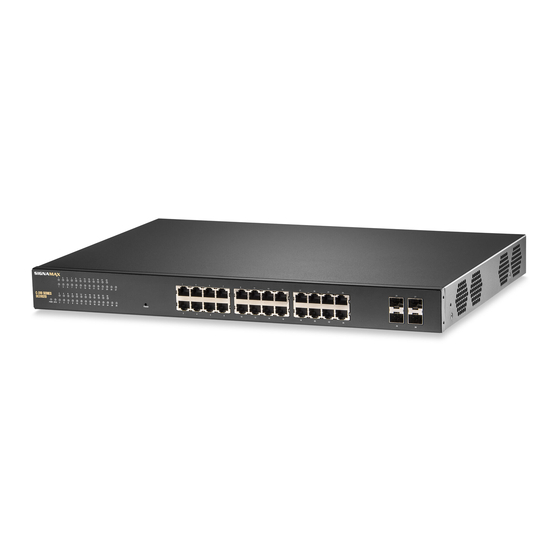
C-310 Series Gigabit Managed Switch
1.
C-310 Series Switch
2.
Rack Mounting Kit—brackets and screws
3.
Power cord—US, Continental Europe, or UK
Note:
The C-310 Series switches are for indoor use only.
Note:
For safety and regulatory information, refer to the
Safety and Regulatory Information document included with
the switch.
Note:
Other documentation, including the Installation
Guide, Web Management Guide, and CLI Reference
Guide, can be obtained from www.signamax.com
Note:
The switch drawings in this document are for
illustration only and may not match your particular switch
model.
1. Mount the Switch
Mounting the Switch in a Rack
2
1.
Attach the brackets to the switch using the included screws.
2.
Use the screws and cage/clip nuts supplied with the rack to
secure the switch in the rack.
Caution:
Installing the switch in a rack requires two people.
One person should position the switch in the rack, while the
other secures it using the rack screws.
Note:
The switches can also be installed on a desktop or
shelf using the included adhesive rubber feet.
2. Ground the Switch
1
2
1.
Ensure the rack on which the switch is to be mounted is properly
grounded and in compliance with ETSI ETS 300 253. Verify that
there is a good electrical connection to the grounding point on
the rack (no paint or isolating surface treatment).
www.signamax.com
1
1
Package Contents
2
4.
Four adhesive rubber feet
5.
Documentation—Quick Start Guide (this document) and
Safety and Regulatory Information
2.
Attach a lug (not provided) to a #12 AWG (PoE switch) or #18
AWG (non-PoE switch) minimum grounding wire (not provided),
and connect it to the grounding point on the switch rear panel.
Then connect the other end of the wire to rack ground.
Caution:
unless all supply connections have been disconnected.
Caution:
access location. It should have a separate protective
earthing terminal on the chassis that must be permanently
connected to earth to adequately ground the chassis and
protect the operator from electrical hazards.
3. Connect Power
1.
Plug the AC power cord into the socket on the rear of the switch.
2.
Connect the other end of the power cord to an AC power
source.
4. Verify Basic Switch Operation
1
1.
Verify basic switch operation by checking the system LEDs.
When operating normally, the Power and System LEDs should
be on green.
– 1 –
3
4
The earth connection must not be removed
The device must be installed in a restricted-
1
2
5
E102020-CS-R01
Advertisement
Table of Contents

Related Manuals for SignaMax C-310 Series


Summary of Contents for SignaMax C-310 Series
- Page 1 Safety and Regulatory Information Attach a lug (not provided) to a #12 AWG (PoE switch) or #18 Note: The C-310 Series switches are for indoor use only. AWG (non-PoE switch) minimum grounding wire (not provided), Note: For safety and regulatory information, refer to the and connect it to the grounding point on the switch rear panel.
- Page 2 VCCI Class A Humidity Operating: 10% to 90% (non-condensing) Immunity EN 55024:2010+A1:2015 IEC 61000-4-2/3/4/5/6/8/11 Power Specifications Safety CB (IEC/EN60950-1) AC Input 100–240 VAC, 50-60 Hz, 15 A Power 770 W maximum Consumption PoE Power 740 W Budget – 2 – www.signamax.com...
Need help?
Do you have a question about the C-310 Series and is the answer not in the manual?
Questions and answers