Advertisement
Available languages
Available languages
INSTALLATION INSTRUCTIONS AND OWNER'S MANUAL
READ ALL INSTRUCTIONS CAREFULLY BEFORE STARTING THE INSTALLATION
PLEASE RECORD THE SERIAL NUMBER ________________ OF SHOWER BASE
Important: The Acrylic Shower Base was carefully inspected
and packed for shipment. You should check your unit and if
there are any problems, contact your dealer before installation.
Protect the base and walls from dirt and damage by leaving the
polyethylene protective film in place until installation and other
related construction is complete.
NOTE: Remove the protective film around the flange during
installation prior to drywall and tile application.
Follow Local Building Codes.
E
A
F
B
FIGURE 1- FRAME
LAYOUT DIMENSIONS
TOOLS AND MATERIALS REQUIRED
Tools: Tape Measure, Electric Drill, Drill Bit (3/16"), Level, Hole
Saw and Caulking Gun
Materials: Mildew Resistant Silicone Bathroom Caulking,
Drywall Screws and Shims (if required).
CAUTION:
If installing walls on the shower base:
Use correct size hole saw based on selected fixture design.
"
Cut from the finished side of the unit.
"
Use masking tape to mask the surrounding surface to
"
prevent scratches and other damages.
General Installation Notes
Note: Dimensions are for framed openings. Refer to
specification sheet for specific product dimensions.
The Shower Base is to fit into framed alcove as shown in
!
Figure 1 and Figure 2.
Rough-in dimensions: See reference below
!
Chart A - Bases Installation
Chart B - Bases & Walls Installation
Framing: Inside dimension of the studded alcove are to
!
be as specified in Figure 1.
©
Copyright 2010
Mirolin Ind.
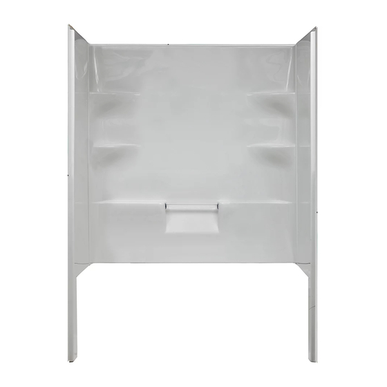
ELLIS SERIES BASE
ELLIS SERIES - BASE & WALLS
SAVE THIS MANUAL FOR FUTURE REFERENCE
C
D
The Copyright includes all content on the document
Shimming May Be Required
The unit will rest on the front edge and the two legs at the
!
rear. Shims may be required to level the shower base to
ensure adequate drainage.
The shower base is fastened in place using dry wall screws.
!
Holes are to be drilled in the flange on both sides and across
the top. The holes are to be drilled by the installer as
illustrated in figures 3 - 6 on the following pages.
CHART A - BASES INSTALLATION
MODEL 60X36
60X32 48X36
A
22"
22"
B
60 1/4"
60 1/4"
15"
C
17 1/4"
D
36 1/4"
32 1/4"
80"
80"
E
7 3/4"
7 3/4"
F
CHART B - BASES & WALLS INSTALLATION
MODEL 60x32
48x36
22"
22"
A
60 1/4"
48 1/4"
B
15"
17"
C
32 1/4"
36 1/4"
D
80"
80"
E
24"
7 3/4"
F
31"
27"
G
Note: All Framing Dimensions + / - 1/4"
D
G
Wall Flange
Dry Wall
EB 60 x 32 L shown
FIGURE 2 - SHOWING THE TOP VIEW OF THE BASE IN THE ALCOVE.
.
mirolin.com
22"
48 1/4"
17"
36 1/4"
80"
24"
G
1
Advertisement
Table of Contents

Subscribe to Our Youtube Channel
Related Manuals for Mirolin ELLIS Series


Summary of Contents for Mirolin ELLIS Series
- Page 1 ELLIS SERIES BASE mirolin.com ELLIS SERIES - BASE & WALLS INSTALLATION INSTRUCTIONS AND OWNER’S MANUAL READ ALL INSTRUCTIONS CAREFULLY BEFORE STARTING THE INSTALLATION PLEASE RECORD THE SERIAL NUMBER ________________ OF SHOWER BASE SAVE THIS MANUAL FOR FUTURE REFERENCE Important: The Acrylic Shower Base was carefully inspected Shimming May Be Required and packed for shipment.
-
Page 2: Installation Steps
PREPARATION Build solid framing to the dimensions in figure 1. If it is an existing alcove, shimming may be required in order to install walls and base section plumb and square. Silicone Make sure that the vertical and horizontal studs on the side Caulking wall is at the dimension as shown in figure 1 and 2. -
Page 3: Maintenance
Install Shower Door according to the manufacturer’s 8 screws at instructions if purchased back wall Mirolin Industries Corp. is not responsible for any damages incurred as a result of poor installation of the product. Screw flange on the 2”x4” stud... - Page 4 Structure: Les dimensions de l'alcôve munie de ses montants doiventêtre celles spécifiées sur la figure 1. FIGURE 2 – VUE DE DESSUS DE LA BASE DANS L'ALCÔVE. © Copyright 2010 Mirolin Ind. Le Copyright comprend tout le contenu de ce document...
-
Page 5: Étapes D'installation
PRÉPARATION: & Construire une structure solide selon les dimensions de la figure 1. & Lorsqu'il s'agit d'une alcôve existante, il peut être nécessaire de caler afin d'installer les murs et la section de bas d'aplomb et Produit d'étanchéité à d'équerre. base de silicone &... -
Page 6: Entretien
Poser une garniture sur la périphérie du bac de la douche pour finir la cloison sèche, si nécessaire. Installer la porte de douche (en cas d'achat) selon les directives du fabricant. Mirolin Industries Corp. n'assume aucune responsabilité en cas de dommages résultant d'une mauvaise utilisation du produit.
Need help?
Do you have a question about the ELLIS Series and is the answer not in the manual?
Questions and answers