Table of Contents
Advertisement
Available languages
Available languages
Quick Links
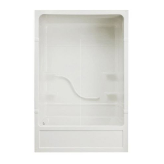
Parker
- Tub Shower
TM
Please record product serial number.
PT516L/R, PT520L/R
PT513L/R, PT523L/R
IMPORTANT
The Acrylic Tub Shower was carefully inspected and packed for
shipment. You should check your unit and if there are any
problems, contact your dealer before installation.
Protect the tub shower from dirt and damage by leaving the
polyethylene protective film in place until installation and other
related construction are complete.
1 PC FRAME
3 PC FRAME
TOOLS AND MATERIALS REQUIRED
Tools: Tape Measure, Electric Drill, Drill Bit (3/16"), Level, Hole Saw
and Caulking Gun
Materials: Mildew Resistant Silicone Bathroom
Caulking, Drywall Screws and Shims (if required).
CAUTION
Assembly and installation of this shower unit requires 2 persons.
To cut plumbing fixture openings on the tub shower unit:
Use correct size hole saw based on selected fixture design.
Cut from the finished side of the unit.
Use masking tape to mask the surrounding surface to prevent
scratches and other damages.
Installation GUIDE
Parker
TM
- 1 Piece Tub Shower
-
Parker
TM
- 3 Piece Tub Shower
-
-
FIGURE 1
LAYOUT
DIMENSIONS
Save manual for future reference.
S N
General Installation Notes
NOTICE
Dimensions are clear openings. Refer to specification sheet for
dimensions of shower unit.
The Tub Shower is to fit into formed recess as shown in Figure 1 and 2.
Clear opening is required with the flange outside of the opening: 1 PC -
57 ½" x 88 ½" and 3 PC- 57 ½ "X84 ½"
Rough- in dimensions: 1PC- 60"x90" and 3PC- 60"x86"
Framing: Inside dimension of the studded alcove are to be as specified
in Figure 1.
Follow Figure 2 as specified to ensure width is 57 ½" between the 2" x
2" recessed studs. (See detail view.)
Shimming May Be Required
The unit will rest on the front edge and the two legs at the rear of the
unit. Shims may be required to level the tub to ensure adequate
drainage. Insert the bottom section in the alcove and shim accordingly.
Then remove and assemble as per instructions.
The shower is fastened in place using dry wall screws. Holes are to be
drilled in the flange on both sides and across the top. The holes are to
be drilled by the installer, installation is illustrated in figures 3 and 3A.
If there is a gap at the seam on the front post, then shim the flange as
illustrated in Figure 3B.
2ʺ x 4ʺ
WOOD BLOCK
DRYWALL
8 ½ʺ
216 mm
FIGURE 2
Page 1 - 8
2ʺ X 2ʺ
WOOD BLOCK
DRYWALL
SCREW
3/8ʺ
TUB FLANGE
57 ½ʺ
1461 mm
60 ½ʺ
1537 mm
R0084314, Rev B
Advertisement
Table of Contents

Subscribe to Our Youtube Channel
Related Manuals for Mirolin Parker PT516L/R


Summary of Contents for Mirolin Parker PT516L/R
- Page 1 Parker - Tub Shower INSTALLATION GUIDE Please record product serial number. PT516L/R, PT520L/R Parker - 1 Piece Tub Shower Parker PT513L/R, PT523L/R - 3 Piece Tub Shower General Installation Notes IMPORTANT NOTICE Dimensions are clear openings. Refer to specification sheet for ...
- Page 2 FIGURE 3A STUD FIGURE 3B SHIM FIGURE 3 - FASTENING WITH DRYWALL SCREWS FIGURE 4 - DRYWALL FINISHING Remove the protective film from the tile flange before fastening. SNAP-FIT SYSTEM ASSEMBLY INSTRUCTIONS NOTICE To the Installer - Please remove all the shims from the Snap Fit extrusions of the unit prior to installation. 1.
- Page 3 Fill the bath with water and leave it for one hour to ensure that the adjustment of the drain-overflow assembly is correct, and that there are no leaks. NOTICE Mirolin Industries Corp. is not responsible for any damages incurred as a result of poor installation of the product. MAINTENANCE The acrylic sheet, which forms the surface of your bathtub, provides one of the most durable surfaces found in modern bathrooms.
- Page 4 Parker - Baignoire-douche GUIDE D’INSTALLATION Veuillez entrer le numéro de série du produit. PT516L/R, PT520L/R Parker - 1 Pièce Baignoire-douche PT513L/R, PT523L/R Parker Baignoire-douche - 3 Pièce Notes d'installation générales IMPORTANT Les baignoires en acrylique a été soigneusement inspectées et ...
- Page 5 ILLUSTRATION 3A montant cale ILLUSTRATION 3B ILLUSTRATION 3 - FIXATION DU VIS DE CLOISON SÈCHE Retirer le film protecteur du rebord pour carreaux de céramique avant fixation. ILLUSTRATION 4 - FIXATION DU CLOISON SÈCHE DIRECTIVES D’INSTALLATION DU SYSTÈME SNAP-FIT AVIS A l'Installateur - enlève s'il vous plaît tous les cales de support du Claquement les extrusions Capables de l'unité...
- Page 6 Remplir le bain d’eau et la laisser pendant une heure pour s’assurer de la pose correcte du drain / trop-plein et de l’absence de fuite. AVIS Mirolin Industries Corp. n'assume aucune responsabilité en cas de dommages résultant d'une mauvaise utilisation du produit. ENTRETIEN La feuille d’acrylique qui constitute la surface de la cabine fournit l’une des surfaces les plus durables que l’on puisse trouver dans les salles de bain...
- Page 7 AND CLEANING INSTRUCTIONS. Mirolin Industries Corp. shall not be liable for any damage to the product resulting from reasonable wear and tear, outdoor use, misuse (including ADDITIONAL RIGHTS...
- Page 8 Mirolin Industries Corp. recommande à l’autre. d’embaucher un plombier professionnel pour toute installation et Ceci est la garantie écrite exclusive de Mirolin Industries Corp. et la réparation. Nous vous recommandons également d’utiliser de véritables garantie n’est pas transférable.
Need help?
Do you have a question about the Parker PT516L/R and is the answer not in the manual?
Questions and answers