
Related Manuals for Kraus Indy KSB-10001


Summary of Contents for Kraus Indy KSB-10001
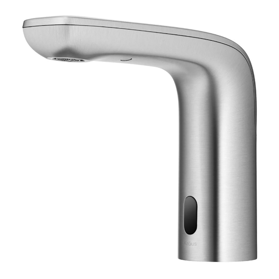
- Page 1 INSTALLATION MANUAL Indy™ Hands-Free Bath Faucet with Sensor KSB-10001 www.kraususa.com I Toll Free: 1.800.775.0703 I © 2023 Kraus USA Plumbing LLC I Rev. March 29, 2023...
- Page 2 Congratulations on the purchase of your new Kraus plumbing fixture! Please keep the box and packaging materials until your product is completely installed. If you have any questions, require technical assistance or have any problems with your product: DO NOT RETURN TO STORE...
-
Page 3: Prior To Installation
Make sure you have all necessary parts by checking the diagram and · parts list. If any part is missing or damaged, please contact Kraus Customer Service at 800-775-0703 for a replacement. Read all instructions and safety warnings and ensure you have all tools, ·... - Page 4 Diagram and Parts List F. Mixing Valve A. Faucet Body G. Hose B. Washer H. Sensor Control Box C. Nut I. Battery Pack D. Spanner Key J. "AA" Battery E. Quick Connector K. Filter Washer...
-
Page 5: Faucet Dimensions
Faucet Dimensions 6 3/8" [162.7mm] 1 7/8" 4 5/8" [48.1mm] [119.0mm] 5 1/2" 4 1/2" [138.9mm] [114.4mm] 1 7/8" 2 7/8" [48.1mm] [73mm] 3/8" compression 3/8" compression 16" [406.4mm] 2 1/4" 3/8" compression [58.3mm] 1 3/4" [46.0mm] Installer Tip: Shut off main water supply before installing new faucet. -
Page 6: Step 2: Installing The Faucet
Step 1: Remove washer and nut Shut off the water supply. Remove the old faucet. Before installation, remove the washer (B) and the nut (C) from the faucet by unscrewing the nut (C) in a counterclockwise direction. Step 2: Installing the faucet Install the faucet body (A), supply hoses (1) and sensor cable (2) through the hole in the sink or countertop. - Page 7 Step 3: Securing the faucet assembly 3.2. Thread the lock nut (C) onto the bolt 3.1. Install the washer (B) onto the threaded bolt. using the spanner key (D) provided to tighten firmly. Do not overtighten. Step 4: Installing the sensor control box Install the sensor cable (1) to the control box connection (2).
- Page 8 Step 5: Hose installation - Hot and Cold water Hot and cold water adjustable mode (optional): Thread the nuts (1) on the inlet hose (G) onto the mixing valve (F) and tighten with a wrench. Do not overtighten. Connect the mixing valve (F) with the red tag to the quick connector on the sensor control box (H) with a matching red tag.
-
Page 9: Step 7: Installing The Battery Pack
Step 6: Hose installation - Cold water only Single cold water mode (optional): Thread the nut (1) on the hose (G) onto the quick connector (E) and tighten with a wrench. Do not overtighten. Connect the quick connector (E) with the red tag to the hose on the sensor control box (H) with a matching red tab. - Page 10 Step 7: Installing the battery pack - continued Drill a hole in the wall using a 6 mm (15/64 in.) diameter drill bit. Install the battery pack (I) using the molly anchor (1) and screw (2) provided. Insert the battery pack cable (3) into Black the control box connection (4).
- Page 11 Step 9: Connect waterlines to main valve - Cold water only Thread the nut (1) on the supply line onto the outlet of the water supply valve (2) and tighten with a wrench. Do not overtighten. Only perform this step on the cold water side. NOTE: This step is for the water supply connections using single cold water mode.
- Page 12 Step 11: Operating the sensor Turn the water on by activating the sensor (1) min. by keeping your hand within 4 inches of the sensor. When removing your hand from within 4 3/4 inches of the sensor, the water will turn off. The initial water outlet temperature is the coldest state.
-
Page 13: Replacement Parts
Replacement Parts Replacement Parts List Finish / Color Part # 1. Aerator KP27163 2.Quick connector assembly KP27328 3. Metal washer KP27198 4. Nut KP27327 5. Spanner Key KP27329 6.Connector assembly KP27330 7. Mixing Valve KP27331 8.O-Ring KP27092 9. Block KP27073 10. -
Page 14: Troubleshooting
Troubleshooting If you have followed the instructions carefully and your faucet still does not work properly, take the following corrective steps: Problem 1: The light on the sensor is flashing continuously. Replace the batteries Flash continuously and slowly Turn on the water supply and move your hand in the sensor area. If the sensor flashes continuously and slowly, then replace the 4 "AA"... - Page 15 Problem 3: There is a low flow of water. mixing valve Connector washer This could indicate that the washer in the "in" end of the There is a low flow of water control box is dirty or damaged. Remove the mixing valve or LED indicator in the and unscrew the connector.
- Page 16 Kraus warrants the structure and finish of the Faucet to be free from defects in material and workmanship under normal usage for as long as the original purchaser resides in the residence in which the Faucet was first installed.
- Page 17 TO THE MAXIMUM EXTENT PERMITTED BY APPLICABLE LAW, THIS WARRANTY DOES NOT COVER, AND KRAUS USA PLUMBING, LLC SHALL NOT BE LIABLE FOR, ANY SPECIAL, INCIDENTAL OR CONSEQUENTIAL DAMAGES (INCLUDING LABOR CHARGES TO REPAIR, REPLACE, INSTALL OR REMOVE THIS PRODUCT), WHETHER ARISING OUT OF BREACH OF ANY EXPRESS OR IMPLIED WARRANTY, BREACH OF CONTRACT, TORT, OR OTHERWISE.
- Page 18 IMPORTANT Register Your Kraus Product Activate Your Warranty Access Premium Customer Support Get Product Information REGISTER TODAY http://www.kraususa.com/registration www.kraususa.com...
Need help?
Do you have a question about the Indy KSB-10001 and is the answer not in the manual?
Questions and answers