Bosch B426 Installation And Operation Manual
Conettix ethernet communication module
Hide thumbs
Also See for B426:
- Installation manual ,
- Installation and operation manual (38 pages) ,
- Setup & troubleshooting (23 pages)

Related Manuals for Bosch B426


Summary of Contents for Bosch B426
- Page 1 Conettix Ethernet Communication Module B426 Installation and Operation Guide (UL)
-
Page 3: Table Of Contents
Table of Contents | en Module Table of contents Safety Introduction About documentation Bosch Security Systems, Inc. product manufacturing dates System overview Overview Bus address settings Installation Mount the module in the enclosure Mount and wire the tamper switch (optional) -
Page 4: Safety
Safety ESD Precaution Please note that the B426 board comes without any case/box and all components are exposed for finger touches - therefore extra attention must be paid to ESD (electrostatic discharge) precaution. Make sure there is no static interference when using the board. Appropriate ESD protections must be taken and wearing electrostatic equipment is recommended, such as anti- static wrist strap. -
Page 5: Introduction
Bosch Security Systems, Inc. product manufacturing dates Use the serial number located on the product label and refer to the Bosch Security Systems, Inc. web site at http://www.boschsecurity.com/datecodes/. The following image shows an example of a product label and highlights where to find the manufacturing date within the serial number. -
Page 6: System Overview
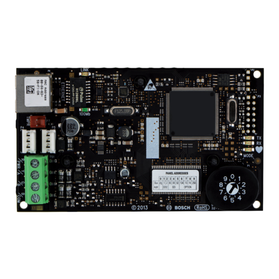
System overview Warning! Failure to follow these instructions can result in a failure to initiate alarm conditions. Bosch Security Systems, Inc. is not responsible for improperly installed, tested, or maintained devices. Follow these instructions to avoid personal injury and damage to the equipment. - Page 7 Conettix Ethernet Communication System overview | en Module Callout ᅳ Description Callout ᅳ Description 1 ᅳ Compatible Bosch control panel 8 ᅳ Ethernet network connection to the Ethernet adapter (D6680/ITS-D6682/ ITS-D6686) (ITS-D6682 shown) Ethernet Network Adapter 2 ᅳ Data bus connection between the control 9 ᅳ...
-
Page 8: Overview
IPv6 or IPv4 Ethernet networks. The B426 on-board switch determines the bus address of the device. Configuration of the B426 is performed through the B426 configuration web pages. On SDI2 control panels, configuration can also be done on the keypad or through Remote Programming Software (RPS). - Page 9 The B426 address switch provides the value for the module's address. The figure below shows the address switch setting for address 1. Refer to the table below for panel-specific settings.
-
Page 10: Installation
B426 module overview, page 8. Wire to the control panel When you wire a B426 to an SDI or SDI2 control panel, you can use either the module's terminal strip labeled R, Y, G, B (PWR, A, B, COM) or the module's interconnect wiring connectors (wire included). - Page 11 1 ᅳ SDI2 control panel. For SDI control panels, wire R, Y, G, B to the SDI bus. 2 ᅳ Module 3 ᅳ To Ethernet network 4 ᅳ Terminal strip wiring 5 ᅳ Interconnect cable (P/N: F01U079745) (included) Bosch Security Systems, Inc. Installation and Operation Guide (UL) 2013.08 | 02 | F.01U.281.208...
- Page 12 1 ᅳ Compatible control panel (FPD-7024 control panel shown) 2 ᅳ Module 3 ᅳ To Ethernet network 4 ᅳ Terminal strip wiring For complete wiring instructions, refer to the control panel documentation. 2013.08 | 02 | F.01U.281.208 Installation and Operation Guide (UL) Bosch Security Systems, Inc.
-
Page 13: Configuration
Conettix Ethernet Communication Configuration | en Module Configuration You can configure the B426 using one of the methods described in this section for your control panel type. Configure for SDI2 control panels Notice! By default, when connecting a field replacement B426 to an existing SDI2 control panel, the control panel overrides the module settings. -
Page 14: Determine A Module's Hostname Or Ip Address
If the module is connected directly to a computer (laptop or PC) and is not connected to a network (no network hub, router, or switch is connected), you can use the module's AutoIP feature to assign a static IP address to the module. 2013.08 | 02 | F.01U.281.208 Installation and Operation Guide (UL) Bosch Security Systems, Inc. - Page 15 Using the AutoIP: Direct connect the B426 to the Ethernet port on a computer and wait 60 sec. If AutoIP service is enabled on your PC, a 169.254.XXX.XXX address should now be assigned to your PC.
-
Page 16: Use Web-Based Configuration Menus
Open an internet browser (Microsoft Internet Explorer 6 or higher, or Mozilla Firefox 3 or higher), type in the B426’s IP address or hostname, and press [Enter]. (If Web and Automation Security is enabled on the B426, you must type https:// instead of http://). -
Page 17: Change And Save Settings Using The Web
Whereas DHCP requires a DHCP server, AutoIP does not require a server when selecting an IP address. A host configured with AutoIP receives an IP address of 169.254.xxx.xxx. Bosch Security Systems, Inc. Installation and Operation Guide (UL) 2013.08 | 02 | F.01U.281.208... - Page 18 DNS server’s IP address. Alternate IPv4 DNS Server IP Address Default: 0.0.0.0 Selection: 0.0.0.0 to 255.255.255.255 This parameter provides an alternate IPv4 DNS server IP address. 2013.08 | 02 | F.01U.281.208 Installation and Operation Guide (UL) Bosch Security Systems, Inc.
- Page 19 Each octet has a value 0-255. When this is defined through the DHCP service, leave the default value. TCP/UDP Port Number Bosch Security Systems, Inc. Installation and Operation Guide (UL) 2013.08 | 02 | F.01U.281.208...
-
Page 20: Advanced Network Settings Page
Advanced Network Settings page Figure 5.4: Advanced Network Settings page Legacy Panel Mode Default: 0 (Disable) Selections: 0, 1 0: Legacy Panel Mode is disabled. 2013.08 | 02 | F.01U.281.208 Installation and Operation Guide (UL) Bosch Security Systems, Inc. -
Page 21: Panel Address Settings Page
The Panel Address Setting option only works when the address rotary switch on the module is set to 0 (local configuration setting). If the address switch is set to a position other than 0, the set address is displayed. Bosch Security Systems, Inc. Installation and Operation Guide (UL) 2013.08 | 02 | F.01U.281.208... -
Page 22: Encryption And Security Settings Page
Use this option to enable or disable Advanced Encryption Standard (AES) encryption on the module. Notice! Do not enable encryption in the module for B Series control panels as encryption is done in the panel settings. 2013.08 | 02 | F.01U.281.208 Installation and Operation Guide (UL) Bosch Security Systems, Inc. -
Page 23: Maintenance Page
Selections: Disable, Enable This parameter enables enhanced security for Automation and B426 Web Access. When enabled, HTTPS is applied to B426 Web Access changing the default value of the HTTP port number parameter. This setting also enables TLS Security for Automation. - Page 24 Firmware Upgrade Enable Default: No Selections: Yes, No Yes: Allows firmware upgrades to the B426 using the network. No: Prevents firmware upgrades. Enable or disable the ability to upgrade the module's firmware from the Firmware Upgrade configuration page.
-
Page 25: Factory Default Page
To upgrade the firmware in the module, select the Firmware Update option from the configuration home page. The Firmware Update page opens. Figure 5.9: Firmware Update page Bosch Security Systems, Inc. Installation and Operation Guide (UL) 2013.08 | 02 | F.01U.281.208... -
Page 26: Exiting The Web-Based Configuration Pages
To save the configuration changes that you made, click OK. A confirmation message appears. Figure 5.11: Save and Execute confirmation To exit the configuration web page, click Logout, and then close the internet browser window. 2013.08 | 02 | F.01U.281.208 Installation and Operation Guide (UL) Bosch Security Systems, Inc. -
Page 27: Maintenance And Troubleshooting Leds
Conettix Ethernet Communication Maintenance and troubleshooting LEDs | en Module Maintenance and troubleshooting LEDs The B426 includes the following on-board LEDs to assist with troubleshooting: – Heartbeat (system status). – Data bus communication. – Ethernet communication. Flash pattern Function Flashes once every 1 sec Normal state: Indicates normal operation state. -
Page 28: Show The Firmware Version
Flashing 100Base-TX activity ON Steady Table 6.3: Ethernet Link LEDs descriptions Refer to B426 module overview, page 8 for Ethernet link LED descriptions. Show the firmware version To show the firmware version using an LED flash pattern: – If the optional tamper switch is installed: With the enclosure door open, activate the tamper switch. -
Page 29: Specifications And Certifications
Microsoft Internet Explorer 6 or higher, Mozilla Firefox 3 or higher. Compatible control panels B Series GV4 Series GV3 Series GV2 Series G Series Version 6.3 or higher Bosch Security Systems, Inc. Installation and Operation Guide (UL) 2013.08 | 02 | F.01U.281.208... -
Page 30: Certifications
B5512/B4512/B3512, Systems GV4 Series, GV3 Series, GV2 Series CAN/ULC S304 - Signal Receiving Centre and Premise B5512/B4512/B3512, Alarm Control Units GV4 Series, GV3 Series, GV2 Series 2013.08 | 02 | F.01U.281.208 Installation and Operation Guide (UL) Bosch Security Systems, Inc. - Page 31 ULC-ORD C1076 - Proprietary Burglar Alarm Units and B5512/B4512/B3512, Systems GV4 Series, GV3 Series, GV2 Series ICES-003 - Digital Apparatus B5512/B4512/B3512, GV4 Series, GV3 Series, GV2 Series Bosch Security Systems, Inc. Installation and Operation Guide (UL) 2013.08 | 02 | F.01U.281.208...
- Page 34 Bosch Security Systems, Inc. 130 Perinton Parkway Fairport, NY 14450 www.boschsecurity.com © Bosch Security Systems, Inc., 2013...
Need help?
Do you have a question about the B426 and is the answer not in the manual?
Questions and answers