Bosch B901 - Access Control Interface Module Installation Manual
- Installation manual (2 pages)
Advertisement
- 1 Overview
- 2 Address settings
- 3 Installation
- 4 Configuration
- 5 LED descriptions
- 6 Show the firmware version
- 7 Specifications
- 8 Documents / Resources
Overview
The B901 Access Control module is a fully supervised SDI2/SDI device that allows access control integration for compatible control panels. Each module can store up to 2000 user tokens (on SDI2), each with a different access level for each door. Authority for access is controlled by the user's authority level, the time of day, the state of the door, and the armed state to the module.
| Compatible Credential Formats | |
| 37 bit | HID H10304 (With Site Code) |
| 37 bit | HID H10302 (No Site Code) |
| 26 bit | HID H10301 EM-EM4200 (3-byte or 5-byte) |

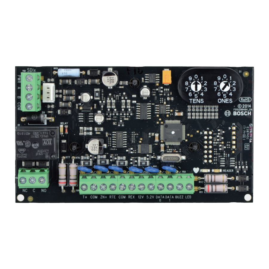
| Callout ― Description |
| 1 ― Terminal connector |
| 2 ― Interconnect wiring connectors |
| 3 ― Address switch |
| 4 ― Reader LED |
| 5 ― Heartbeat LED (blue) |
| 6 ― Reader and door terminals |
| 7 ― Relay terminals |
| 8 ― Relay LED |
Address settings
Two address switches determine the address for the B901 Access Control Module. The control panel uses the address for communications. The address also determines the output numbers. Use a slotted screwdriver to set the two address switches.

NOTICE!
The module reads the address switch setting only during power up. If you change the switches after you apply power to the module, you must cycle the power to the module in order for the new setting to be enabled.

Set the address switches per the control panel configuration. If multiple B901 modules reside on the same system, each B901 module must have a unique address. Figure 2.1 shows the address switch settings for address 01.
Valid addresses for SDI2
Valid B901 addresses are dependant on the number of modules allowed by a particular control panel.
| Control panel | Valid B901 addresses | Designation |
| B9512G/B9512G-E | 01 - 32 | Devices 1 - 32 |
| B8512G/B8512G-E | 01 - 08 | Devices 1 - 8 |
| Control panel | Valid B901 addresses | Designation |
| B6512 | 01 - 04 | Devices 1 - 4 |
Valid addresses for SDI
Valid B901 addresses are dependant on the number of modules allowed and the desired failure mode (Fail Safe, Fail Secure) by a particular control panel.
| Control panel | Valid B901 addresses | Designation |
| B9512G/B9512G-E/ B8512G/B8512G-E D9412GV4/D7412GV4 D9412GV3/D7412GV3 D9412GV2/D7412GV2, D9000 | 81 - 88 | Devices 1 - 8 Fail Safe mode = door unlocked |
| 91-98 | Devices 1 - 8 Fail Secure = door locked |
Installation
After you set the address switch for the proper address, install the module in the enclosure, and then wire it to the control panel.

Remove all power (AC and battery) before making any connections. Failure to do so might result in personal injury and/or equipment damage.
NOTICE!
B901 tamper generates an SDI - "Missing Door" or an SDI2 - "Module Tamper" message (if Enclosure Tamper parameter is set to Yes).
Mount the module in the enclosure
Mount the module into the enclosure's 3-hole mounting pattern using the supplied mounting screws and mounting bracket. Refer to Figure 3.1.

| Callout ― Description |
| 1 ― Module with mounting bracket installed |
| 2 ― Enclosure |
| 3 ― Mounting screws (3) |
Mount the access card reader
Refer to your access card reader installation instructions for proper installation and maintenance procedures related to your supported card reader.
Wire to the SDI2 control panel
When you wire the module to a control panel, use the control panel terminals labeled R, Y, G, B (PWR, A, B, COM). Connect them to the module terminals labeled R, Y, G, B (PWR, A, B, COM). Use either terminal strip wiring or interconnect wiring connector to the control panel. Do not use both. Refer to Figures 3.2 - 3.3.

| Callout ― Description |
| 1 ― Bosch control panel (B9512G shown) |
| 2 ― Terminal wiring |
| 3 ― B901 Access Control Module |
| 4 ― Interconnect cable (P/N: F01U79745) (included) |
Wire to the SDI control panel

| Callout ― Description |
| 1 ― Bosch control panel (GV3 shown) |
| 2 ― Terminal wiring |
| 3 ― B901 Access Control Module |
| 4 ― Interconnect cable (P/N: F01U79745) (included) |
Wire to the card reader
Use the terminals labeled LED, DATA1, DATA0, 5.2V or 12V, COM, and T+ when wiring the module to a card reader. Refer to Figure 3.4.

| Callout ― Description |
| 1 ― Card reader (ARD-AYK12 shown) |
| 2 ― Terminal wiring |
| 3 ― B901 Access Control Module |
Wire to 12VDC power supply (optional)
Refer to Figure 3.5 to wire additional power to a regulated powerlimited power supply for fire protective signaling units and commercial/ residential burglar units.

| Callout ― Description |
| 1 ― Control panel COM terminal (B9512G shown) |
| 2 ― 12 VDC regulated power-limited power supply (B520 shown) |
| 3 ― Terminal wiring (PWR and COM terminal wiring) |
| 4 ― B901 Access Control Module |
NOTICE!
Use only Access Control listed power supplies for powering door strikes.
Wire to the door strike
A relay provides a dry contact single pull double throw output. Some strikes require a closed circuit to unlock the door, while others require an open circuit to unlock the door.
- Common (C). For 12/24 VDC strikes, provide input power here from the power supply. Refer to Figure 3.6.
- Normally closed (NC). For door strikes that require an interruption of power to open. Connect the positive side of the door strike to the NC terminal. Refer to Figure 3.6.
- Normally open (NO). For door strikes that require power to open.
Connect the positive side of the door strike to the NO terminal. Refer to Figure 3.6.


| Callout ― Description |
| 1 ― Door |
| 2 ― B901 door lock relay terminal |
| 3 ― B901 terminal |
| 4 ― AUX PWR terminal (12 VDC) (B520 shown) |
| 5 ― Door strike (12 VDC) |
Wire to door contact

| Callout ― Description |
| 1 ― Door Contact |
| 2 ― 1k EOL |
| 3 ― B901 Access Control Module |
Request to Enter (RTE)
Wire the Request to Enter (RTE) device. The strike is activated, and the door point is shunted when RTE is momentarily shorted to COM. The Shunt only option shunts the point when this input is momentarily shorted. To activate the shunt but not the strike, program RTE Shunt Only? as [YES].

| Callout ― Description |
| 1 ― RTE device |
| 2 ― B901 Access Control Module |
Request to Exit (REX)
Wire the Request to Exit (REX) device.

| Callout ― Description |
| 1 ― REX device |
| 2 ― B901 Access Control Module |
The strike is activated, and the door point is shunted when REX is momentarily shorted to COM. The Shunt only option shunts the point when this input is momentarily shorted. To activate the shunt but not the strike, program REX Shunt Only? as [YES].
NOTICE!
Do not use a Request to Exit device (REX) for emergency exit applications. NFPA 101 requires that a UL Listed panic device be used to provide direct power from the standby power source. Check with your local Authority Having Jurisdiction (AHJ) prior to installing your system.
Configuration
After you wire the module, power up the system and configure the B901 using Remote Programming Software (RPS) to assign the module to an assigned area. Whenever possible, be consistent when numbering doors, areas, and keypads. For example, assign Door 1 to Area 1 and keypad 1. Test for proper operation.
LED descriptions
The module includes one blue Heartbeat LED, and one Reader LED. The Heartbeat LED indicates that the module has power as well as a module's current state. The Reader LED indicates data transmission. Refer to Table 5.1.
Table 5.1: LED descriptions
| Flash Pattern | Function |
Flashes once every 1 sec | Normal state: Indicates normal operation state. (blue) LED trouble state: Module is not powered |
ON Steady | |
OFF Steady | (for OFF Steady only), or some other trouble condition prohibits the module from communicating with the control panel. |
Flashes rapidly | Card data is executing (yellow) |
OFF Steady | No card data is being received |
Show the firmware version
To show the firmware version using an LED flash pattern:
- If the optional tamper switch is installed:
With the enclosure door open, activate the tamper switch (push and release the switch). - If the optional tamper switch is NOT installed: Momentarily short the T+ terminal.
Refer to Figure 6.1 for an example of flash patterns.


When the tamper switch is activated, the heartbeat LED stays OFF for 3 sec before indicating the firmware version. The LED pulses the major, minor, and micro digits of the firmware version, with a 1 sec pause after each digit.
In the following example, the version 1.4.3 shows as LED flashes:
[3 sec pause] *___****___*** [3 sec pause, then normal operation].
NOTICE!
Firmware reprogramming on the B901 is not supported if connected via the SDI bus. Updating the firmware is achieved via the SDI2 connection only.
Specifications
| Dimensions | 2.9 in x 5.0 in x 0.6 in (73.5 mm x 127 mm x 15.25 mm) |
| Voltage (input) | 12 VDC nominal |
| Current | Standby: 110 mA + reader current Alarm: 110 mA + reader current |
| Alarm output | Form C relay (NC, COM, NO) at 12/24 V @ 2.0 A |
| Operating temperature | 0°C to +50°C (+32°F to +122°F) |
| Relative humidity | 5% to 93% at +32°C (+90°F) non-condensing |
| Terminal wire size | 18 AWG to 22 AWG (1.02 mm to 0.65 mm) |
| SDI2/SDI wiring to B901 + Reader with external power supply | Maximum distance - wire size (unshielded wire only): 1000 ft (305 m) - 22 AWG (0.65 mm), 2500 ft (762 m)
|
| SDI2/SDI wiring to B901 + Reader from control panel | 175 ft (53 m) - 22 AWG (0.65 mm), 450 ft (137 m) - 18 AWG (1.02 mm) |
| Wiring distance from B901 to Reader | 200 ft (61 m) - 22 AWG (0.65 mm), 500 ft (152 m) - 18 AWG (1.02 mm) Reader dependant |
| Bosch compatible control panels | B9512G/B9512G-E/B8512G/B8512G-E/B6512/ D9412GV4/D7412GV4/D9412GV3/D7412GV3/ D9412GV2/D7412GV2/D9412G/D7412G (Refer to the control panel installation document for the number of supported devices.) |
| Bosch compatible readers and accessories | ARD-AYH12 EM Prox Wall Mount ARD-AYJ12 EM Prox Mullion ARD-AYK12 EM Prox Mini Mullion ARD-AYQ12 EM Prox Wall Mount Vandal Resistant ARD-AYCE65B EM Prox or PIN Mullion ARD-R10 HID iClass Mini Mullion ARD-R40 HID iClass Wall Mount D8223 HID Prox Wall Mount D8224 HID Prox Mullion D8224-SP HID Prox Switch Plate Mount D8225 HID Prox Mini Mullion D8229 PIN Reader |
| Bosch compatible credentials | ACA-ATR13 EM Tokens* ACD-ATR11ISO EM Cards* ACD-ATR14CS EM Clamshell Cards ACD-IC2K26-50 iClass Cards** ACT-IC2K26-10 iClass Tokens** D8236-10 HID Prox Cards*** D8236KF-10 HID Prox Tokens*** |
| * EM cards work with EM readers, ** iClass cards work with iClass readers, *** Prox cards work with Prox readers | |
Bosch Security Systems, Inc.
130 Perinton Parkway
Fairport, NY 14450
USA
www.boschsecurity.com
Bosch Sicherheitssysteme GmbH
Robert-Bosch-Ring 5
85630 Grasbrunn
Germany

Documents / Resources
References
Download manual
Here you can download full pdf version of manual, it may contain additional safety instructions, warranty information, FCC rules, etc.
Download Bosch B901 - Access Control Interface Module Installation Manual
Advertisement


Need help?
Do you have a question about the B901 and is the answer not in the manual?
Questions and answers