
Subscribe to Our Youtube Channel
Related Manuals for inbody 170


Summary of Contents for inbody 170
- Page 1 InBody170 USER’S MANUAL Thank you for purchasing the InBody170. Please read manual prior to use and operate with care. Make sure to keep this manual for future reference.
- Page 2 E-mail : info @ inbody.com Acknowledgements Biospace, InBody, Lookin’ Body are the registered trademarks of Biospace Co., Ltd. The names of the companies and products in this manual other than those of Biospace Co., Ltd. are the trademarks of the companies. Stating the products of other companies is strictly for the purpose of providing information, and not to guarantee or recommend the products.
- Page 3 Biospace has earned recognition in the international market for technical expertise demonstrated through the InBody series. Based on the experience and technology over the last 10 years, Biospace has released the body composition analyzer, the InBody170 . With direct segmental measurement, the InBody170 guarantees high accuracy and reproducibility.
- Page 4 Contents How to use this manual Ⅱ Ⅲ Safety Information Indicators & Safety Symbols Ⅶ Workplace Requirements Ⅷ Chapter 1 Installation & Maintenance Chapter 4 Problems & Solutions 1. Contents of the Box 1. Error Messages 2. Exterior & Functions 2.
- Page 5 3. If you have clinical issues while using the InBody170, please contact Biospace customer service. E-mail : info@inbody.com TEL: 82-2-501-3939 4. Read symbols carefully. The following are representations of these symbols. Important information to warn of situations which might cause major injury and/or damage to property if instructions are not carefully followed.
- Page 6 Safety Information 1. Do not use this equipment in combination with the following electronic medical devices. - Medical devices, such as a pacemaker - Electronic life support systems, such as an artificial heart/lung - Portable electronic medical devices, such as an electrocardiograph. 2.
- Page 7 9. Do not dismantle the equipment or open the back cover. Internal parts are not for customer use. If the equipment is dismantled, the warranty is void, and service costs will be charged. If service is required, contact Biospace or the supplying agency. 10.
- Page 8 4. This product must be installed on a flat and stable floor. If the floor is not level, may cause harm or incorrect measurement. 5. Make sure you use the AC adapter provided by Biospace. Using other AC adapter may cause the malfunction of product.
- Page 9 2. Excessively high or low temperatures, humidity and pressure may affect the equipment operation and may cause error. Please use the equipment within the suggested specification range for equipment’s use. 3. While moving, installing, or using this product, be sure to protect against any physical shock or damage.
- Page 10 Indicators & Safety Symbols Disposal of old Electrical & Electronic Equipment (Application in the European Union and other European countries with separate collection system.) This symbol indicates that this product shall not be treated as household waste. Instead, it shall be handed over to the applicable collection point for the recycling of electrical and electronic equipment.
- Page 11 Workplace Requirements Operation Environment 10 ~ 40 ℃ (50 ℉ ℉ Temperature range ~ 104 ) Relative humidity 30 ~ 75 % Atmospheric pressure range 70 ~ 106 kPa □ Transport and Storage Environment -20 ~ 70 ℃ (-4 ℉ ℉...
- Page 12 Chapter1. Installation & Maintenance 1. Contents of the box 2. Exterior & Functions 3. Installation Instructions 4. Transportation 5. Repacking 6. Maintenance...
- Page 13 1. Contents of the box When opening the box, make sure all of the following items are inside. ① InBody170 ② Joint Screw 1EA ③ Joint Cover ④ Thermal Printer ⑤ Screws 4EA ⑥ Thermal Printer Paper ⑦ Thermal Printer Cable ⑧...
- Page 14 To prevent physical shock, use Biospace’s packing material when shipping or transporting the equipment. Refer to this Chapter, Section 4: “Transportation.” Save the wrapping material after unpacking for the event of relocation.
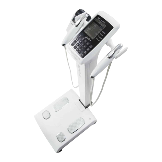
- Page 15 2. Exterior & Functions Individual part identification and functions with schematic sketches are provided below. Please inspect each component of the InBody170 for damage prior to installation. A. Operation Part (Head) B. Stand Part C. Base Part D. Rear Part A.
- Page 16 A. Operation Part (1) LCD This displays the analysis procedure, messages and results. (2) Key Pad (19 buttons) The keypad is divisible into input buttons and function buttons. These are used to input data required for body composition analysis, to set up the operating environment and to print out test results.
- Page 17 (4) Palm Electrode Activated by wrapping the palm around the electrode, thus allowing current to flow through the body during measurement. (5) Hand Electrode Cable The hand electrode cable is connected to the circuit that transfers voltage and electric current. Please be careful, applying excessive force on the cable attached to the hand electrode may damage the product.
- Page 18 C. Base Part Joint Cover Bubble level indicator Front Sole Electrode Rear Sole Electrode Joint Screw Foot Plate Level Screws (1) Front Sole Electrode Activated by placing the fore-foot directly on the front sole electrode. This allows the current to flow through the body. (2) Rear Sole Electrode Activated by placing the heel of the foot directly on the rear sole electrode.
- Page 19 (5) Joint Screw This is the joint screw which fixes the upper part in such a way it does not move. (6) Bubble Level Indicator Used to level the InBody170 by means of a view glass and bubble alignment. <Unleveled state> <Leveled state>...
- Page 20 D. Rear Part (1) Back Cover Only qualified personnel are allowed to remove the back cover. Do not dismantle the equipment. Internal parts are not for customer use and may cause electric shock. If the equipment is dismantled, the warranty is void, and service costs will be charged.
Need help?
Do you have a question about the 170 and is the answer not in the manual?
Questions and answers