Advertisement
Quick Links
Auber Instruments, Inc.
This assembling guide only provides basic guidance on how to assemble the parts in KIT‐CUBE5E together. The
person who attempts to assemble the KIT‐CUBE5E should have basic knowledge of electrical circuits, can
understand wiring diagrams, and can use tools such as a multimeter, screwdrivers, and etc.
Before you start the assembling process, please read the wiring diagram of Cube5E and understand each part is
wiring to the circuit.
We use the "Wiring Kit" of KIT‐CUBE5E in this assembling process.
1. Preparation
1.1. Parts
Please see the part list included with the kit.
1.2. Tools
Flat‐end punches (or similar) and a small hammer (for removing knockouts)
Phillips screw drivers
Flat‐head screw drivers
Adjustable wrench or socket wrenches
Pliers
Multimeter (for troubleshooting, if needed)
2. Installing Components
2.1. Disassemble the Enclosure
Remove the bottom plate (Figure 2‐1‐a) and the back plate (Figure 2‐1‐b) by removing the
screws pointed by the red arrows.
Figure 2‐1‐a
No part of this manual shall be copied, reproduced, or transmitted in any way without the prior, written consent of Auber Instruments. Auber
Instruments retains the exclusive rights to all information included in this document.
KIT-Cube5E Assembling Guide
Version 0.9
(2023‐04‐21)
Copyright 2007‐2023, Auber Instruments. All Rights Reserved.
www.auberins.com
Figure 2‐1‐b
Advertisement

Related Manuals for Auber Instruments KIT-Cube5E


Summary of Contents for Auber Instruments KIT-Cube5E
- Page 1 Auber Instruments, Inc. www.auberins.com KIT-Cube5E Assembling Guide Version 0.9 (2023‐04‐21) This assembling guide only provides basic guidance on how to assemble the parts in KIT‐CUBE5E together. The person who attempts to assemble the KIT‐CUBE5E should have basic knowledge of electrical circuits, can understand wiring diagrams, and can use tools such as a multimeter, screwdrivers, and etc. Before you start the assembling process, please read the wiring diagram of Cube5E and understand each part is wiring to the circuit. We use the “Wiring Kit” of KIT‐CUBE5E in this assembling process. 1. Preparation 1.1. Parts Please see the part list included with the kit. 1.2. Tools Flat‐end punches (or similar) and a small hammer (for removing knockouts) Phillips screw drivers Flat‐head screw drivers Adjustable wrench or socket wrenches Pliers Multimeter (for troubleshooting, if needed) 2. Installing Components 2.1.
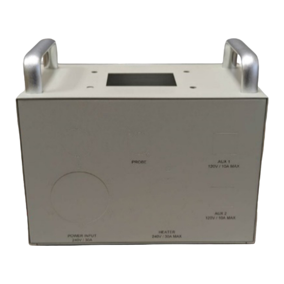
- Page 2 Auber Instruments, Inc. www.auberins.com 2.2. Remove the Knockouts There are a few knockout holes on the back‐plate and one knockout hole on the front of the enclosure that need to be removed. Please see Figure 2‐2‐a and Figure 2‐2‐b for the final result after all the knockouts are removed. Use flat‐end punches (Figure 2‐2‐c) and a hammer to remove the knockouts as shown in Figure 2‐2‐d. Figure 2‐2‐a Figure 2‐2‐b Figure 2‐2‐c Figure 2‐2‐d 2.3. Install Components to the Back‐Panel Identify the power connectors and the XLRCON‐M connector from the parts you received, install them to their knockout holes as shown in Figure 2‐3 (a) and (b). Please note that only the two NEMA 5‐15R sockets are snap‐in connectors, other connectors should be tightened to the back‐panel by screws. Page 2 of 11 ...
- Page 3 Auber Instruments, Inc. www.auberins.com Figure 2‐3‐a Figure 2‐3‐b 2.4. Install Fuse Blocks Install the two fuse blocks to the left side of the enclosure. For each fuse block, first align the small anti‐rotation tab and the screw hole with the holes on the enclosure (Figure 2‐4‐a), then secure the fuse block using the M3 screw and nut (Figure 2‐4‐b). Make sure the fuse block is not removing around, then install the fuse. Figure 2‐4‐a Figure 2‐4‐b 2.5. Install Components to the Front‐panel Install the two selector switches (SW4) to the two AUX switch holes on the front plate. Align the selector’s two switch positions with the “OFF” and the “ON” markers on the front plate. Each of the SW4 is tightened by two screws, one on the top and one on the bottom as shown in Figure 2‐5‐a. Tightened these two screws till the switch is secure and won’t rotate. Install the push‐button switch (SW9‐UL) to the knockout hole on the lower front panel of the Cube enclosure. This switch is tightened by a hex nut as shown in Figure 2‐5‐a. Insert the supplied wiring harness (WH‐16) to this switch. You can remove the red wire for the normally closed (N.C.) pin from the wiring harness as shown in Figure 2‐5‐b. Page 3 of 11 ...
- Page 4 Auber Instruments, Inc. www.auberins.com Figure 2‐5‐a Figure 2‐5‐b Install the EZboil controller to the center hole on the front plate. Install the two wood screws supplied with EZboil controller to help secure the mounting bracket against the front plate (Figure 2‐5‐c). Figure 2‐5‐c 2.6. Install the SSR and the Heatsink Place the silicone heat‐transfer pad on the heatsink (Figure 2‐6‐a), then place the solid‐state relay (SSR) on the pad, use two of the M4 screws to fix the SSR to the heatsink. Place the heatsink/SSR assembly to the top of the Cube enclosure, install 4 pieces of M6 screws supplied with the kit to secure the heatsink to the top of the enclosure (Figure 2‐6‐b). Page 4 of 11 ...
- Page 5 Auber Instruments, Inc. www.auberins.com Figure 2‐6‐a Figure 2‐6‐b 3. Installing Wires Important Notes on Wiring The color code for 14 AWG and 10 AWG wires o Green: grounding wire o White: neutral wire o Black: hot, L1 line o Red: hot, L2 line Three sizes of wires are used: o 22 AWG wires are control wires that only carry small current. o 14 AWG wire are for AUX sockets that carry less than 15A at 120VAC. o 10 AWG wires are for the main input/output that is less than 30A at 240VAC. 3.1. Install Ground Wires on the Back‐panel Install the ground wires as shown in Figure 3‐1. Use one of the mounting screws on the L14‐ 30R power inlet as the grounding post. 3.2. Install wires to the AUX Sockets Install the hot wire and the neutral wire to each of the AUX sockets (NEMA 5‐15R sockets) as shown in Figure 3‐2. The black wires on the left are the hot wires and the white wires on the right is the neutral wires. ...
- Page 6 Auber Instruments, Inc. www.auberins.com Figure 3‐1 Figure 3‐2 3.3. Install the Neutral Wires and Neutral Wire Bus Use one of the 5‐pole wire connector supplied in the kit as the neutral bus. Each of the white wires on AUX sockets has a bare tip. Insert the bare tip to the 5‐pole connector as shown in Figure 3‐3‐b. Install the pin connector of the 10 AWG white wire to the L14‐30P power inlet and insert the bare tip on the other end to the 5‐pole connector. Identify a piece of 22 AWG white wire from the wiring kit and connect it to the 5‐pole connector. Figure 3‐3‐a Figure 3‐3‐b 3.4. Install L1 and L2 Wires to the Input and the Output Sockets Identify the 4 pieces of long 10 AWG wires from the kit (a shorter black 10 AWG wire is not needed for this step), and install them to the power inlet and the power outlet as shown in Figure 3‐4 (a) and (b). The black wires in the wiring kit are for L1 (line 1) wires and the red wires are for L2 (line 2) wires. Please note that the wires installed to the power outlet (L6‐30R) should have fork connectors, and the wires installed to the power inlet (L14‐30P) should have pin connectors. Page 6 of 11 ...
- Page 7 Auber Instruments, Inc. www.auberins.com Figure 3‐4‐a Figure 3‐4‐b 3.5. Install Wires on the Front Panel Use the other 5‐pole wire connector as the Hot Bus. On the two AUX selector switches (SW4), remove one block from each switch because we only need one block on each. The black wires for this step are 14 AWG wires with fork connector on one end, bare tip on the other end. Install one wire to each switch block and insert the bare tip on other end to the Hot Bus connector (see Figure 3‐5‐a). Next, connect each switch block to the fuse block. The black wires for this step are 14 AWG wires with fork connector on one end, female quick‐disconnect connector on the other end (see Figure 3‐5‐b). On the wiring harness (WH16) of the controller switch (SW9‐UL), there are 4 pieces wires left, black (LED hot), white (LED neutral), green (N.O.), and blue (common). The black and the blue wire from the wiring harness should be inserted to the Hot Bus. The white wire from the wiring harness should be connected to the EZboil controller’s #9, and the green wire from the wiring harness should be connected to controller’s #10 terminal. The wires on the wiring harness don’t have fork connectors installed. (Note: we added fork connectors to the wires connected to the EZboil controller but this step is not required as long as the wires are firmly clamped by the screw terminals.) Page 7 of 11 ...
- Page 8 Auber Instruments, Inc. www.auberins.com Figure 3‐5‐a Figure 3‐5‐b 3.6. Install Wires to the Main Breaker Switch Now there should be a shorter piece of 10 AWG black wire left in the wiring kit. Install it to the Main Breaker Switch’s top left port as shown in Figure 3‐6‐a. Then install the black wire (L1) and the red wire (L2) from the power inlet (L14‐30P) to the lower side of the Main Breaker Switch as shown in Figure 3‐6‐b. Install the red wire (L2) from the power outlet (L6‐30R) to the top left port on the Main Breaker Switch (Figure 3‐6‐b). The black wires should be on the left side of the Main Breaker Switch and the red wires should be on the right side (Figure 3‐6‐c). Figure 3‐6‐a Figure 3‐6‐b Figure 3‐6‐c 3.7. Install the Main Breaker Switch to the Front Panel First, install the bracket of the Main Breaker Switch to the front panel (Figure 3‐7‐a). Turn the breaker (as well as the back‐panel) to the correct orientation and push it into the bracket as shown in Figure 3‐7‐b. Once it is fitted in, the two bottom tabs on the bracket should snap in and hold the breaker in place (Figure 3‐7‐c). Insert the short black wire on the bottom of the breaker to the Hot Bus as shown in Figure 3‐ 7‐c. Page 8 of 11 ...
- Page 9 Auber Instruments, Inc. www.auberins.com Figure 3‐7‐a Figure 3‐7‐b Figure 3‐7‐c 3.8. Connect wires to the solid‐state relay Install the short black 10 AWG wire to the #1 pin on the SSR and install the black 10 AWG wire from the L6‐30R socket to the #2 pin on the SSR (Figure 3‐8‐a). Pre‐bend the wire to a proper shape first, and then insert the fork connector to the screw terminal. Tighten the screw so that the connector is firmly secured. Install the control signal wires between the EZboil controller and the SSR (Figure 3‐8‐b). Please note that the control signal is 12VDC and it has polarity. The positive signal from controller’s #7 should be connected to the SSR’s #3 pin. Figure 3‐8‐a Figure 3‐8‐b 3.9. Connect wires to the EZboil controller Page 9 of 11 ...
- Page 10 Auber Instruments, Inc. www.auberins.com Install the three wires from the probe connector (XLRCON‐M) to the EZboil controller as indicated by the sticker on the controller. The two wires of the same color should be connected to #3 and #4, the other wire to #5 as shown in Figure 3‐9. Identify the 22 AWG white wire on the neutral bus. Connect its fork connector to the #9 pin on the controller. Ensure that another white wire from the switch wiring harness is also firmly installed to the #9 pin on the controller (Figure 3‐9). Figure 3‐9 Figure 3‐10 3.10. Connect AUX Sockets and Fuse Blocks Connect the black 14 AWG wires on the AUX sockets to the corresponding fuse blocks as shown in Figure 3‐10. At this point, all the parts and wires should have been installed. 4. Inspection and Assemble the Cube 4.1. Inspection Check for any loose or free wires, or any mismatch of the wire color between the wiring in your Cube unit and the image in Figure 4‐1. Check the wiring against the wiring diagram. Page 10 of 11 ...
- Page 11 Auber Instruments, Inc. www.auberins.com Figure 4‐1. 4.2. Install the back panel and the bottom cover. Install the back panel first by tighten the two screws on each side as shown in Figure 4‐2. Then put the bottom cover back and install the 8 screws. Figure 4‐2 (End) Auber Instruments, Inc. 5755 North Point Parkway, Suite 99, Alpharetta, GA 30022, USA. www.auberins.com E‐mail: info@auberins.com Tel: 770‐569‐8420 Copyright 2007‐2023, Auber Instruments. All Rights Reserved. No part of this manual shall be copied, reproduced, or transmitted in any way without the prior, written consent of Auber Instruments. Auber Instruments retains the exclusive rights to all information included in this document. Page 11 of 11 ...
Need help?
Do you have a question about the KIT-Cube5E and is the answer not in the manual?
Questions and answers