Advertisement
Quick Links
AUBER INSTRUMENTS
Instruction Manual
Caution
• This controller is intended to control equipment under normal operating
conditions. If failure or malfunction of the controller may lead to abnormal
operating conditions that may result in personal injury or damage to the
equipment or other property, devices (limit or safety controls) or systems
(alarm or supervisory) intended to warn of or protect against failure or
malfunction of the controller must be incorporated into and maintained as
part of the control system.
• This controller carries a one (1) year warranty. This warranty is limited to
the controller only.
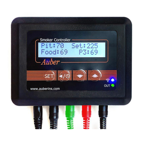
1. Front Panel and Connections on SYL-3615
1. LCD display
2.SET key
3.TIMER/BACK key
4.Down key
5.Up key
12.Power adapter
connector
11.Fan connec tor
Figure 1. Front panel of a SYL-3615 controller.
Figure 2. Connection ports on the bottom of a SYL-3615.
2020.11
SYL-3615 Wi-Fi BBQ Controller Quick Guide
Firmware v0.9.77
Document version 0.9.1 (Nov, 2020)
6. Wi-Fi indi cator
7. Output indicator
8. Pit probe
9. Food probe
10. Probe 3
Table 1. Recognize different parts on a SYL-3615.
Name
Description
#
1
LCD display
Display probe readings, set temperature, and etc.
2
SET key
* Short-press to access cooking profile menu.
* Long-press to access control menu and system
menu.
3
TIMER /
* Check status (step number, time, and output).
BACK key
* Cancel Open-lid status.
4
DOWN key
* Mute the buzzer.
* Scroll down the menu.
* Decrease value.
5
UP key
* Scroll down the menu.
* Decrease value.
6
Wi-Fi indicator
* Solid-on, connected to Wi-Fi.
* Slow-blinking, lost Wi-Fi connection.
* Fast-blinking, ready to pair (AP mode).
7
Output
Indication of the output level to the fan.
indicator
8
Pit Probe
The probe that measures pit temperature
9
Food Probe
A pointed probe can be inserted into food.
10
Probe 3
A third probe for monitoring food temperature.
11
Fan connector
DC connector from the fan, 2.5 mm x 5.5 mm.
12
Power
DC connector, 2.1 mm x 5.5 mm. Supplies 12
adapter
VDC from the power adapter.
connector
13
P1
Sensor port for the pit probe.
14
P2
Sensor port for the food probe.
15
P3
Sensor port for the third probe.
16
Output to Fan
Output port for the fan, 2.5 mm x 5.5 mm.
17
Power-in
Power input socket, 2.1 mm x 5.5 mm.
2. Getting started
2.1. Powering up the device
Simply connect the 12 VDC power adapter to a wall outlet and then plug
the barrel connector (2.1 mm x 5.5 mm) to the power-in socket on the
very left port on the bottom of the SYL-3615 controller (see Figure 2).
The controller's LCD screen should light up and show its model number
and the firmware version (Figure 3a), and then the LCD screen will go to
the normal display mode (Figure 3b). The "-H-" is a sensor error code,
which means no probe is connected or detected.
WWW.AUBERINS.COM
P1/5
Advertisement

Related Manuals for Auber Instruments SYL-3615


Summary of Contents for Auber Instruments SYL-3615
- Page 1 Simply connect the 12 VDC power adapter to a wall outlet and then plug the barrel connector (2.1 mm x 5.5 mm) to the power-in socket on the very left port on the bottom of the SYL-3615 controller (see Figure 2). The controller’s LCD screen should light up and show its model number and the firmware version (Figure 3a), and then the LCD screen will go to the normal display mode (Figure 3b).
- Page 2 Figure 3(a). The display screen when controller is just powered up. 3. Pairing a SYL-3615 to a Wi-Fi Router Important: The Wi-Fi chip in SYL-3615 can only connect to 2.4 GHz Wi-Fi Figure 3(b). The display screen in normal operating mode.
- Page 3 Once you tap on the CONFIRM button, the SSID and settings in each parameter affects execution of a cooking step. The chart password will be sent to the SYL-3615 so that it can log on to in Figure 8 describes how the parameters in a cooking steps affects the your 2.4 GHz Wi-Fi.
- Page 4 Probe 1 offset -99 ~ 100 Probe 2 offset -99 ~ 100 Probe 3 offset -99 ~ 100 Figure 9. How to install the mounting hooks to SYL-3615. Enable or disable the Buzzer On, Off on-board buzzer nFIL Powerline filter...
- Page 5 AUBER INSTRUMENTS WWW.AUBERINS.COM Figure 10. Two mounting hooks installed on the back of a SYL-3615 controller. 7. FAQs 7.1. A probe shows “-H-” when it is plugged in. The “-H-” is a probe input error message, which usually indicates that no probe is connected or the probe is defective.
Need help?
Do you have a question about the SYL-3615 and is the answer not in the manual?
Questions and answers